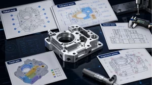
What Tolerance Means in CNC Machining
In CNC machining, tolerance defines how much a measurable value is allowed to vary while the part still performs as intended. The value may be a physical dimension, such as a hole diameter or shaft width, or another measurable parameter. In engineering work, tolerance is a controlled error band: an upper limit, a lower limit, and a decision about what variation can still be accepted.
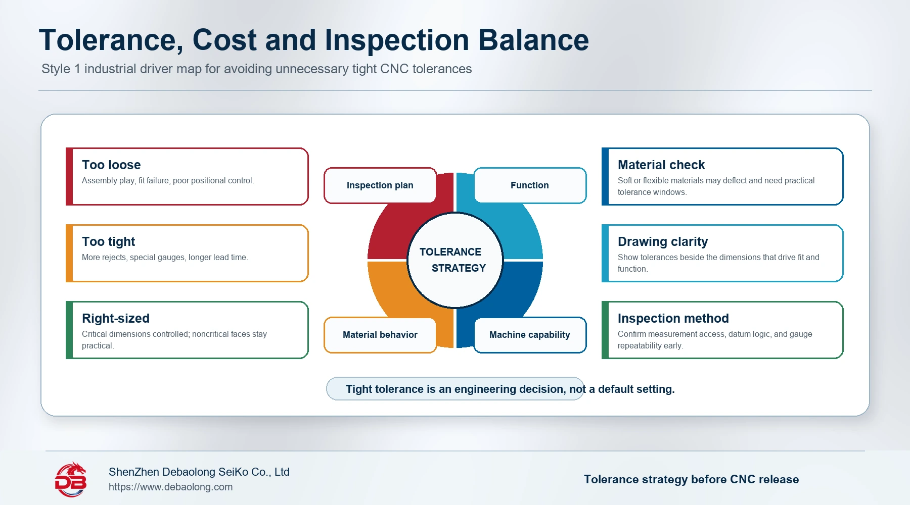
This matters because machined parts rarely exist alone. They fit into assemblies, carry loads, align with other components, and may need to be measured repeatedly during quality control. A tolerance that is too loose can make a part fail at assembly. A tolerance that is tighter than necessary can increase machining time, inspection effort, scrap risk, and cost without improving the real function of the product.
CNC Machine Tolerance vs. Design Tolerance
The source article separates CNC tolerance into two practical meanings: the accuracy capability of the CNC machine, and the tolerance specified by the designer on the part drawing.
Machine tolerance describes what a machine tool can hold under controlled conditions. CNC machining is a highly accurate process, and some machines can achieve precision around +/-0.0025 mm. In normal production planning, however, capability depends on the machine, setup, tool condition, material, geometry, fixturing, and inspection method. A common general machining tolerance around 0.02 mm is often used as a practical reference, but the actual capability should always be confirmed for the process and supplier.
Design tolerance is different. It is the allowable dimensional variation chosen by the part designer based on function, fit, shape, and assembly requirements. For example, a simple door handle can tolerate much more variation than a dense electromechanical assembly with shafts, bearings, housings, and aligned mating features. Design tolerances normally appear next to the controlled dimensions on the drawing.
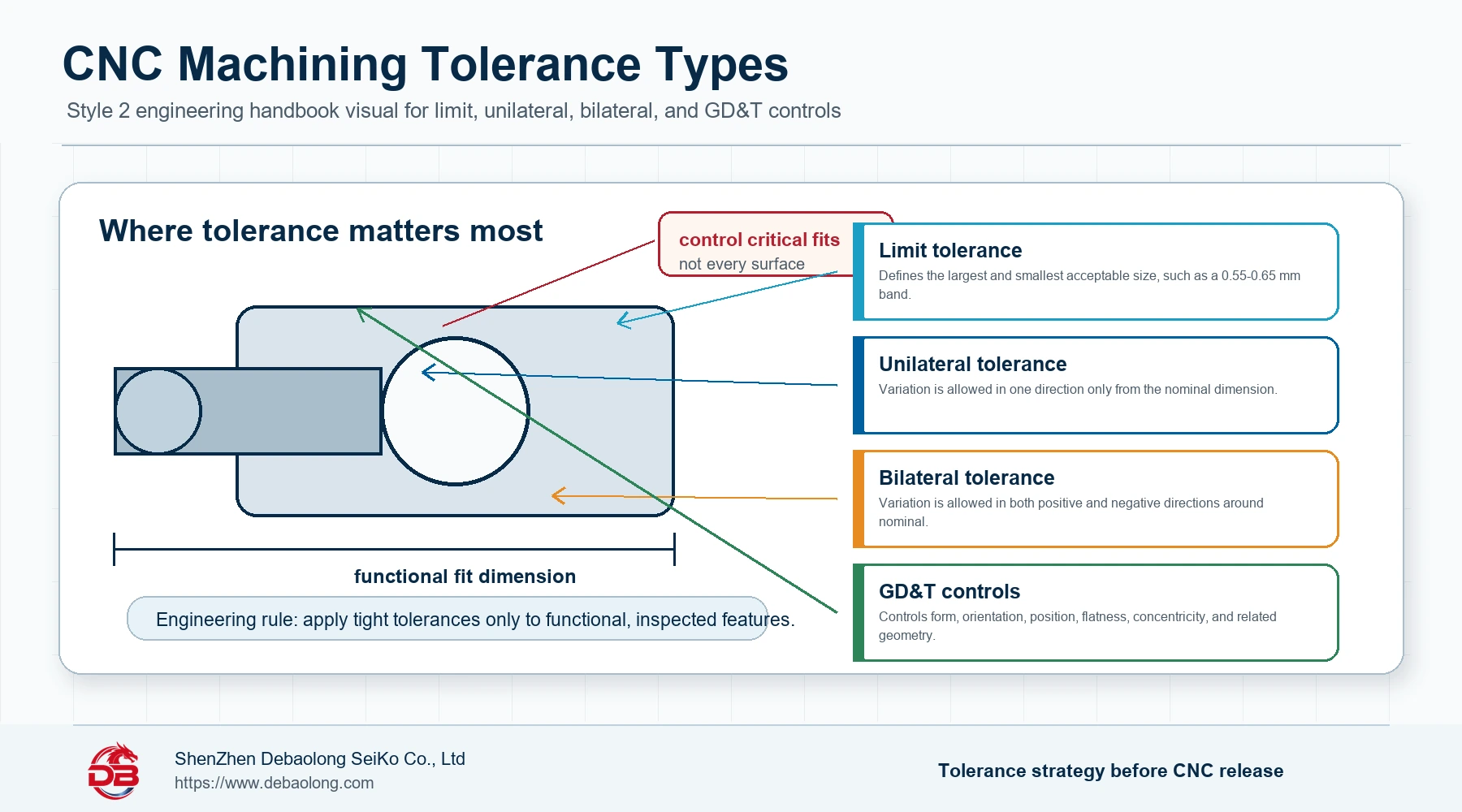
Common Types of CNC Machining Tolerances
Limit Tolerance
Limit tolerance defines the largest and smallest acceptable values for a dimension. If the measured result falls inside that band, the dimension passes. For example, a dimension specified as 0.55-0.65 mm is acceptable anywhere inside that range, and fails outside it.
Unilateral Tolerance
A unilateral tolerance allows variation in only one direction from the nominal value. A dimension such as 1.5 mm +0.000/-0.005 permits the part to be up to 0.005 mm smaller than nominal, but not larger. This is useful when function depends on avoiding material growth in a particular direction.
Bilateral Tolerance
A bilateral tolerance allows variation on both sides of the nominal dimension. When the plus and minus values are equal, the tolerance band is symmetrical around the nominal size. Bilateral tolerances are common when a feature can vary slightly larger or smaller without damaging the fit or function.
GD&T: Geometric Dimensioning and Tolerancing
GD&T is a more advanced tolerance system than simple size tolerancing. It controls not only feature size but also the geometry of points, lines, surfaces, and relationships between features. GD&T can define flatness, position, concentricity, orientation, profile, and other geometric controls. It is especially valuable when the functional relationship between features matters more than a simple plus-minus size callout.
Tolerance Design Tips for Machined Parts
Tolerance design is the engineering step of deciding which features need controlled variation and how tight those limits should be. The most important rule is selective control: not every surface and not every dimension needs a tight tolerance.
- Apply tolerances to critical features. Prioritize mating surfaces, hole patterns, shaft fits, bearing seats, sealing faces, alignment features, and dimensions that directly affect assembly or motion.
- Avoid unnecessary tight tolerances. Tighter requirements often require slower machining, extra inspection tools, dedicated fixtures, more scrap control, and longer lead time.
- Match tolerance to machine capability. A drawing should reflect what the selected machining process can hold reliably, not only what looks ideal in CAD.
- Consider material behavior. Soft, flexible, thin-walled, or stress-relieving materials may be harder to hold to narrow tolerance bands than stable metals or rigid plastics.
- Plan inspection early. A tolerance is only useful if it can be measured consistently. Datum strategy, gauge access, surface finish, and measurement repeatability should be considered before release.
Why Tight Tolerances Increase Cost
Strict tolerances can be essential for high-performance parts, but they should be used deliberately. A tighter tolerance may force slower cutting parameters, more stable fixturing, sharper tooling, controlled temperature conditions, intermediate inspection, or secondary finishing. It may also increase the number of parts rejected during quality control.
For buyers and engineers, the best cost-control practice is to define tolerance based on function. A bearing bore, press-fit hole, precision alignment surface, or sealing interface may need a close tolerance. A cosmetic pocket, clearance edge, non-mating face, or general outside profile may not. Separating critical features from noncritical geometry helps keep the part manufacturable.
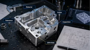
How DEBAOLONG Reviews CNC Tolerance Requirements
For CNC parts, DEBAOLONG reviews tolerance requirements together with material, geometry, workholding, tool access, surface finish, and inspection approach. This is especially important for complex parts where one strict feature can affect the entire setup plan.
Related DEBAOLONG resources include the CNC machining tolerance standards guide, the technical drawing preparation guide, and the DFM prototyping guide. These help connect tolerance callouts to drawings, process planning, inspection, and manufacturing cost.
Conclusion
CNC machining tolerance is not only a number on a drawing. It is a functional agreement between design intent, machine capability, material behavior, inspection method, and cost. The strongest approach is to control the dimensions that truly affect function while keeping noncritical features within practical general tolerances. That balance improves assembly reliability, reduces unnecessary cost, and makes the part easier to manufacture repeatably.
Related Engineering Resources