Shenzhen, China
Find manufacturing processes, materials, finishes, applications and engineering guidance.
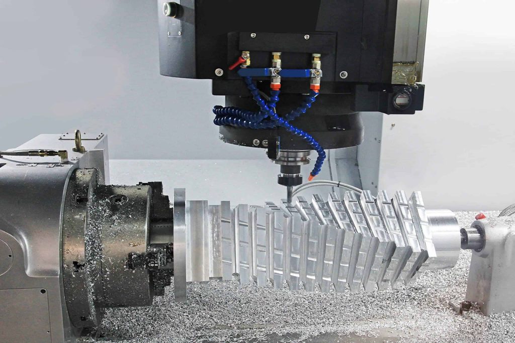
Review milling or turning through setup, material, surface intent and critical interfaces.
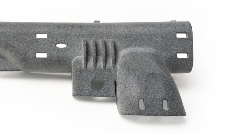
Connect process, orientation, wall, support and post-processing to the part intent.
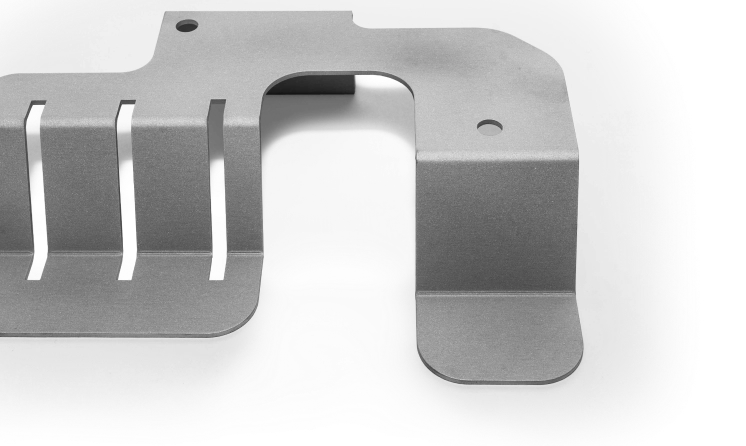
Keep gauge, bend strategy, assembly and finish decisions in one review path.
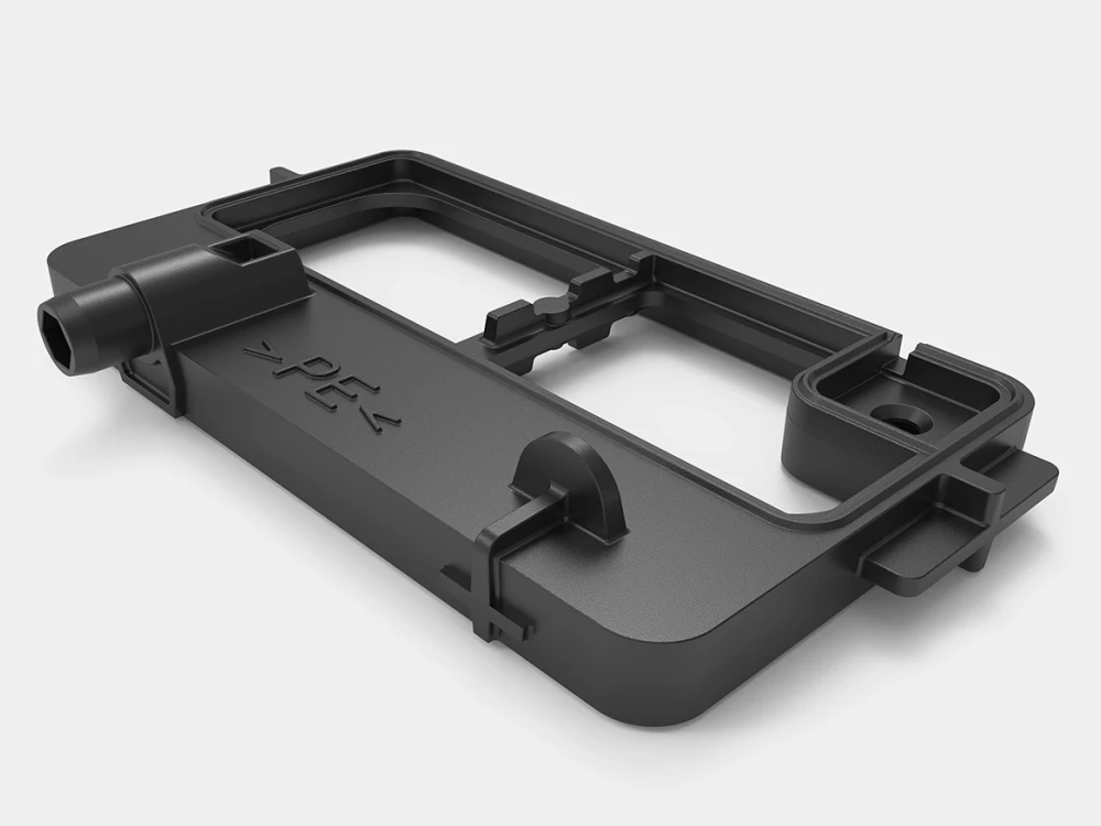
Link part geometry, polymer choice, tooling intent and repeat-production context.

Compare strength, stability, conductivity, machinability and finish relationships.
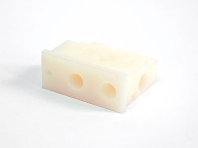
Review moisture, stability, temperature, fit and production-route implications.
Select through process, orientation, geometry and post-processing rather than a name alone.
Material choice stays connected to bend behavior, hardware, assembly and coating.
Compare surface-finishing options by material, function and manufacturing process.
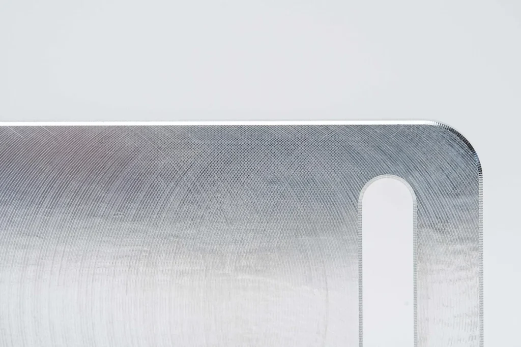
Compare surface goals, material compatibility and process requirements before choosing a finish.

A practical manufacturing partner connecting process, materials, applications and review.
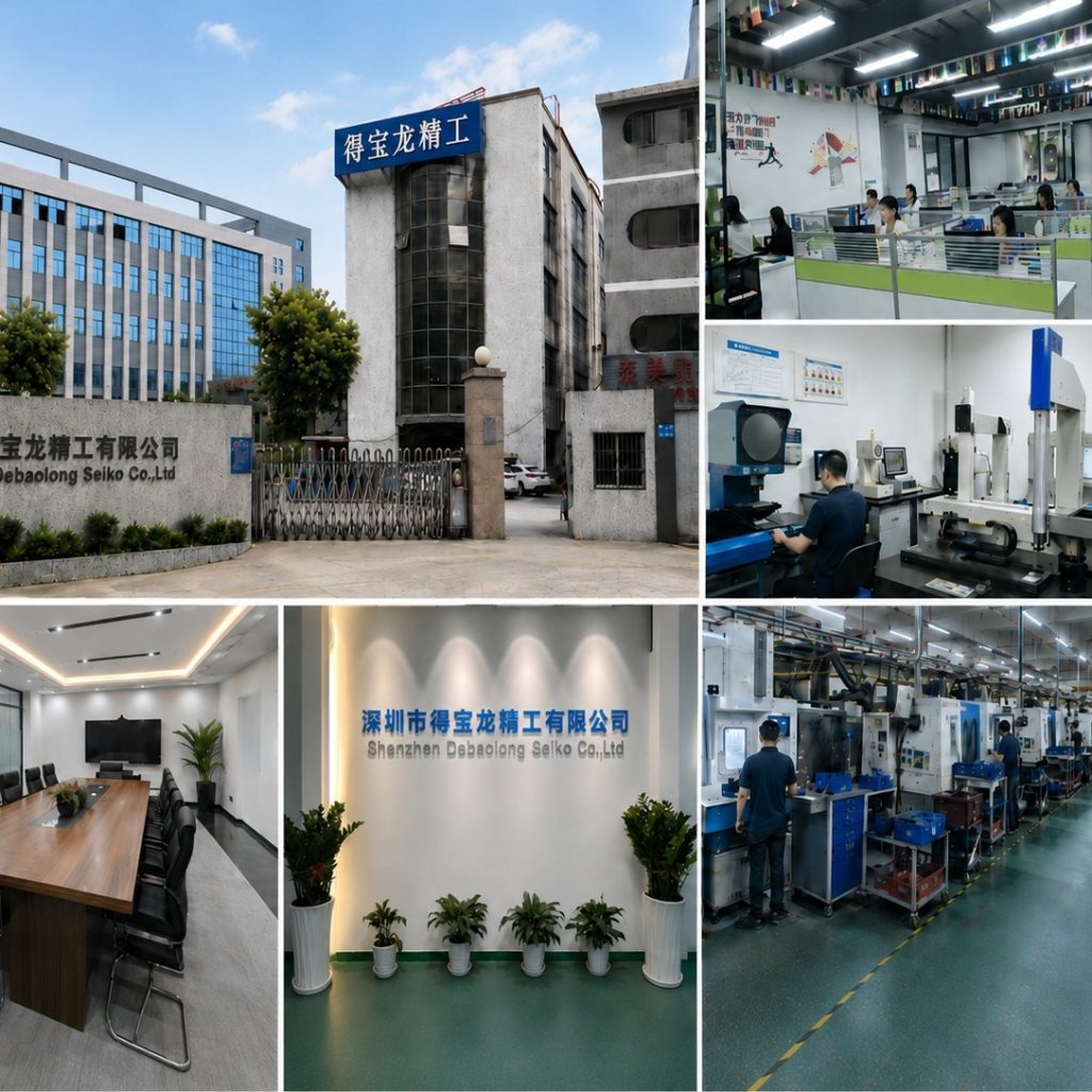
Explore factory context connected to manufacturing routes.
The factory collage shows building, workshop and manufacturing context.
Explore inspection planning connected to manufacturing decisions and engineering review.

An illustrative planning graphic connects critical features, manufacturing decisions and engineering review. It is not a production inspection record.

Use Contact for general conversation or Engineering Review for a project-specific brief.
Coordinate cutting, bending, hardware, joining, coating and formed inspection as one drawing-led fabrication route.
A flat profile becomes a reliable component only when downstream access, bend behavior, hardware and finish zones are considered early.
Profile, holes, nesting, edges and features that will move during forming.
Inserted hardware, weld access and assembly sequence based on the actual component.
Review hardware and access →
Masking, cosmetic faces, conductive zones and post-fabrication handling.
Compare finish routes →
Review the flat and formed state together so holes, slots, edges and interfaces remain practical after bending.
Confirm alloy or grade, thickness, temper or condition and stock requirement.
Locate holes and interfaces with the bend direction, radius and tooling access in mind.
Define which flat or formed features control inspection and assembly.
Mark grain, coating, brush direction and protected faces on the drawing.
Fasteners, inserts, welds and mating interfaces can become inaccessible after forming or coating. The sequence should be explicit.
Material choice and finish must serve the environment, appearance and assembly—not a generic sheet-metal default.
Keep contact, sealing and mating faces visible in the finish plan.
Define color, texture, masking, threads and cosmetic zones.
Specify grain direction and transitions across formed faces.
Confirm environment and compatible protection for the selected base material.
Flat dimensions alone do not confirm a fabricated assembly. Formed geometry, datums, interfaces and visible finish need their own acceptance plan.
Debaolong imagery shows cut, formed, joined and finished outcomes rather than a generic factory collage.
Profiles, bends and interface relationships in finished components.
Review formed-part requirements →
Structures where access and sequence matter.
Review assembly access →
Bare, coated and conductive surface contexts.
Compare surface requirements →
These are review prompts, not universal process promises. The actual drawing and requirement remain authoritative.
Flat features, formed dimensions, datums, hardware, finish zones and critical interfaces.
Before release, because masking, threads, contacts and cosmetic faces affect the manufacturing sequence.
Send component drawings, assembly context, hardware, quantity and inspection expectations together.
Cutting, forming, hardware, joining and coating are interdependent. The drawing should expose where each downstream operation changes access or acceptance.
Compare all four columns. On narrow screens, swipe across the table or focus it and use the arrow keys.
| Stage | Primary question | Drawing input | Acceptance evidence |
|---|---|---|---|
| Cut | Which profiles and edges survive forming? | Flat geometry, material, gauge and edge intent | Profile and feature verification |
| Form | Which bends govern the final interfaces? | Direction, radius, reliefs and formed datums | Angle, location and formed relationship |
| Join / hardware | What becomes inaccessible later? | Hardware, weld, insertion and assembly sequence | Retention, position and assembly fit |
| Finish | Which surfaces remain functional? | Color, texture, masking, threads and contacts | Coverage, protected zones and cosmetic reference |
Hardware and coatings should be reviewed against the actual assembly, not added as independent notes at the end.
Show insertion direction, tool access and neighboring bends.
Identify structural, cosmetic and distortion-sensitive areas.
Protect contacts, threads, gaskets and mating faces.
Measure the formed and finished assembly against its functional datums.
Move between the capability, material, knowledge and project-review paths without repeating the page you just read.
Share CAD, quantity, material, finish and inspection requirements so the route can be reviewed against the actual part.
DEBAOLONG SEIKO · OFFICIAL CHANNEL
Select Play here to preview a video on this page, or Watch on YouTube to open the original.
Video titles describe individual demonstrations; price, time and tolerances are not quotations or general capability commitments.