Why CAD Design Quality Matters in CNC Machining
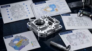
CNC machining can produce accurate, repeatable metal and plastic parts, but the result depends strongly on how the CAD model is prepared. A design that looks complete on screen may still be difficult to machine if it ignores tool access, cutter geometry, wall stiffness, tolerance strategy, material behavior, or drawing communication.
The source article focuses on typical CAD mistakes that make CNC parts harder to manufacture. The most useful lesson is simple: good CNC design is not only about shape. It is about whether the shape can be reached by tools, held securely, inspected clearly and produced without unnecessary cost.
Sharp Internal Corners
One of the most common CNC CAD mistakes is designing sharp internal corners inside pockets or slots. Milling cutters are round, so they naturally leave a radius. If a CAD model shows a perfect zero-radius inside corner, the manufacturer must either use a very small cutter, add extra finishing operations, or modify the design. All of those options can increase cost or risk.
The better approach is to add internal corner radii that match practical cutting tools. Larger radii allow stronger tools, faster machining and better surface quality. When a square corner is functionally required, discuss it early so the feature can be made by EDM, broaching, assembly redesign or another controlled method.
Deep and Narrow Cavities
Deep cavities are not automatically wrong, but deep narrow pockets create tool deflection, vibration, chip evacuation problems and longer machining time. The deeper the tool reaches, the less rigid the setup becomes. Long tools also make it harder to hold tight tolerance and clean surface finish.
Designers should review pocket depth, tool diameter and corner radius together. If a pocket is deep, give the tool enough clearance. Avoid tall vertical walls that force long slender cutters. When possible, open the geometry, split the part, change the assembly concept or use radii that support a stronger tool.
Thin Walls and Weak Features
Thin walls may bend during machining, vibrate under cutting force, overheat or fail inspection after stress relief. This is especially important in aluminum housings, plastic machined parts, bracket ribs and lightweight prototypes. A wall that is acceptable in CAD may not remain stable during clamping and cutting.
The fix is to make walls thick enough for the material and machining method, add ribs where they support function, avoid isolated tall fins and keep thin features away from heavy cutting whenever possible. If weight reduction is necessary, use pocketing and rib geometry that preserve stiffness.
Very Small Holes and Threads
Small holes, deep holes and small threaded features can become expensive if they require fragile tools, long reach drilling or nonstandard taps. Blind threaded holes also need enough bottom clearance for the tap and chips. Designers should check whether the specified hole size and thread depth can be made reliably with standard tools.
Where possible, use standard drill sizes and thread specifications. Avoid over-deep threads unless the strength requirement justifies them. If a hole is functionally critical, call out the tolerance, depth, thread class and inspection requirement clearly on the drawing.
Over-Tight Tolerances
Another common mistake is applying tight tolerance to too many dimensions. CNC machining can hold close tolerance, but every strict requirement must be machined, inspected and controlled. Tolerances that do not affect function add cost without improving the part.
Use tight tolerance only on functional fits, bearing seats, mating surfaces, alignment features, sealing interfaces and dimensions that truly affect performance. General surfaces and cosmetic geometry should use practical tolerances. For related guidance, see DEBAOLONG’s CNC machining tolerance guide.
Ignoring Material Behavior
Material affects tool wear, cutting force, burr formation, deflection and achievable tolerance. A thin wall in aluminum behaves differently from a thin wall in stainless steel or engineering plastic. Some plastics may move with heat or stress relief. Hard metals may need different tool paths and slower machining.
Before release, choose the material for function and manufacturability together. If the material is difficult to machine, compensate with better wall support, larger radii, practical tolerance and realistic surface-finish expectations.
Incomplete Manufacturing Drawings
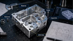
A CAD model alone may not communicate every manufacturing requirement. Drawings should define material, finish, units, critical dimensions, thread notes, inspection datums, surface finish, tolerance class and any special requirements. If this information is missing, the supplier may make reasonable assumptions that do not match design intent.
DEBAOLONG’s technical drawing preparation guide explains how drawings help turn CAD geometry into controlled manufacturing intent. For broader release review, the DFM prototyping guide connects design decisions to cost, quality and schedule risk.
Conclusion
Good CNC CAD design reduces machining risk before the quote, toolpath and inspection plan are created. Avoid sharp internal corners, deep narrow cavities, unstable thin walls, impractical tiny features, unnecessary tight tolerances and incomplete drawings. When geometry, material, tolerance and documentation are aligned, CNC machining becomes faster, more predictable and easier to control.
Related Engineering Resources