Shenzhen, China
Find manufacturing processes, materials, finishes, applications and engineering guidance.
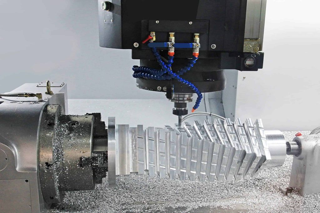
Review milling or turning through setup, material, surface intent and critical interfaces.
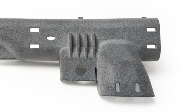
Connect process, orientation, wall, support and post-processing to the part intent.
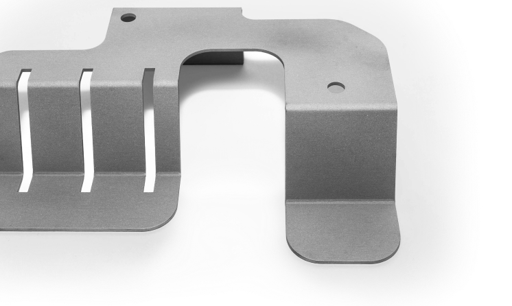
Keep gauge, bend strategy, assembly and finish decisions in one review path.
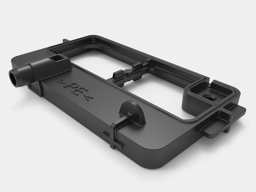
Link part geometry, polymer choice, tooling intent and repeat-production context.

Compare strength, stability, conductivity, machinability and finish relationships.
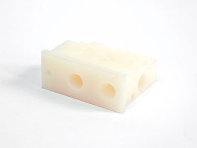
Review moisture, stability, temperature, fit and production-route implications.
Select through process, orientation, geometry and post-processing rather than a name alone.
Material choice stays connected to bend behavior, hardware, assembly and coating.
Compare surface-finishing options by material, function and manufacturing process.
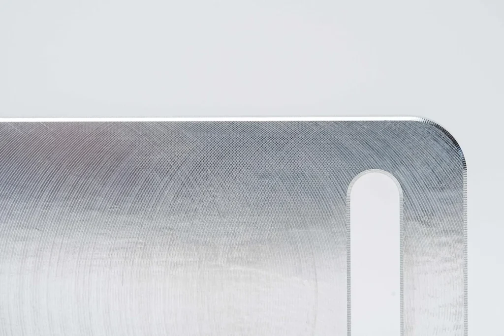
Compare surface goals, material compatibility and process requirements before choosing a finish.

A practical manufacturing partner connecting process, materials, applications and review.
Explore factory context connected to manufacturing routes.
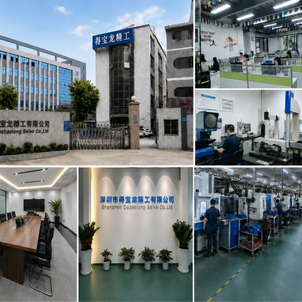
The factory collage shows building, workshop and manufacturing context.
Explore inspection planning connected to manufacturing decisions and engineering review.
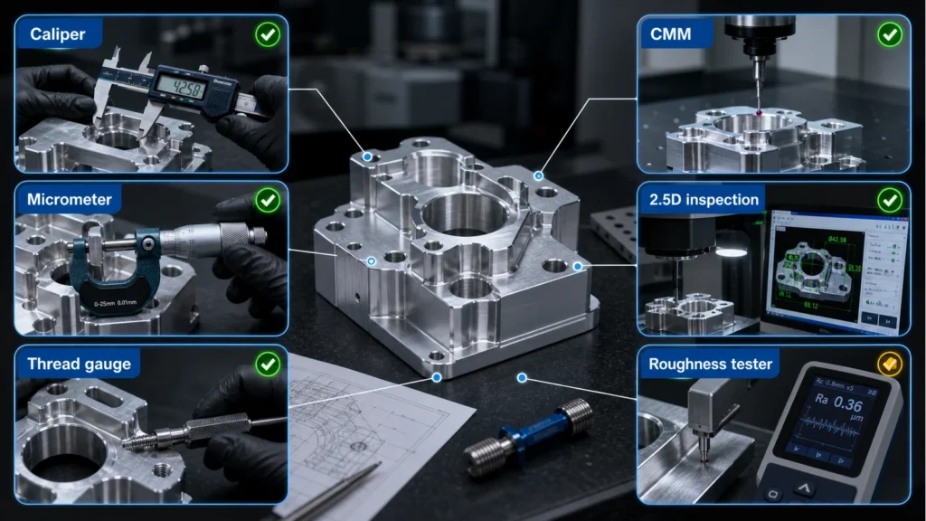
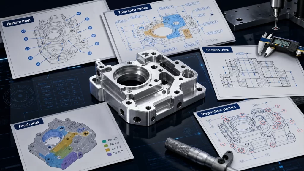
An illustrative planning graphic connects critical features, manufacturing decisions and engineering review. It is not a production inspection record.

Use Contact for general conversation or Engineering Review for a project-specific brief.
Connect resin, wall and draft strategy, gates, parting, inserts, finish, sampling and inspection before committing to a molding program.
Prototype learning, bridge demand and repeat production create different tooling, validation and change-control expectations.
Mold around a prepared insert whose placement and retention must be controlled.
Add a molded material or stage around a substrate with defined interface intent.
A distinct tooling route for suitable flexible-part and sealing requirements.
Wall transitions, draft, ribs, bosses, undercuts and ejection should be reviewed alongside function and cosmetic requirements.
Use a deliberate wall strategy and identify local sections that need review.
Mark surfaces where release, witness and ejection evidence matter.
Protect functional and cosmetic zones by making gate and parting priorities visible.
Connect stiffness, fastening, molding access and assembly intent.
The resin name alone is insufficient. State the performance priorities, appearance, operating environment and any insert or overmold relationship.
Sampling should expose geometry, appearance and dimensional decisions before the process is treated as production-ready.
Document the assumptions that depend on the actual CAD and production stage.
Check fill, visible surfaces, interfaces and key dimensions against the agreed plan.
Separate tool, process and part-design changes so their effect remains traceable.
Carry approved references and critical checks into subsequent runs.
Texture, gloss, gate witness, parting lines and color should be tied to named surfaces and an agreed reference.
Identify visible zones, viewing direction and permitted process witness.
Use references and surface zones rather than broad adjectives alone.
State resin color, masterbatch or comparison reference when applicable.
Call out inserts, assembly, printing or secondary operations explicitly.
Use datums, mating features, appearance zones and approved samples to define acceptance. A generic dimensional report is not the entire molding plan.
These part images show housings, openings and visible interfaces for part-specific discussion. They do not establish tooling capability, inspection results or production approval.
Parts with different walls, interfaces and material expectations.
Review the molding route →
Cosmetic zones, bosses, openings and assembly features.
Explore molding materials →
A finished-part example for discussing visible surfaces, openings and interfaces. Sampling results and production records must be reviewed separately.
Prepare a part review →
These are review prompts, not universal process promises. The actual drawing and requirement remain authoritative.
Production stage, resin priorities, quantity, wall and draft intent, cosmetic surfaces and critical interfaces.
They have different substrate, placement, retention and interface requirements that must be reviewed from the actual part.
Critical dimensions, appearance references, assembly checks and the open issues that remain before repeat release.
The part, resin and tool strategy should remain connected through sampling, corrections and the final acceptance reference.
Compare all four columns. On narrow screens, swipe across the table or focus it and use the arrow keys.
| Review stage | Decision | Evidence captured | Next gate |
|---|---|---|---|
| Part review | Walls, draft, gates, parting and interfaces | Open-risk list tied to CAD surfaces | Tool strategy agreed |
| Tool / process setup | Access, ejection, insert or overmold sequence | Tool and process assumptions | First-sample plan |
| Sampling | Fill, witness, appearance, fit and key dimensions | Sample results and marked deviations | Correction or approval |
| Repeat release | Approved references and critical checks | Revision, material, appearance and inspection record | Controlled production handoff |
Insert molding, overmolding and secondary operations add interface decisions that a resin name cannot answer.
Define insert preparation, orientation, exposed zones and verification.
State the substrate, interface purpose and areas that must remain free.
Protect sealing, cosmetic and assembly-critical surfaces.
Tie appearance to named zones and an agreed comparison.
Move between the capability, material, knowledge and project-review paths without repeating the page you just read.
Share CAD, quantity, material, finish and inspection requirements so the route can be reviewed against the actual part.