Engineering review for every RFQ
CNC · 3D Printing · Sheet Metal · Injection Molding
Prototype · Low Volume · Production
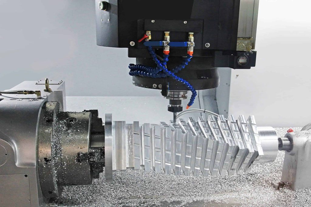
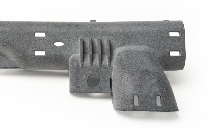
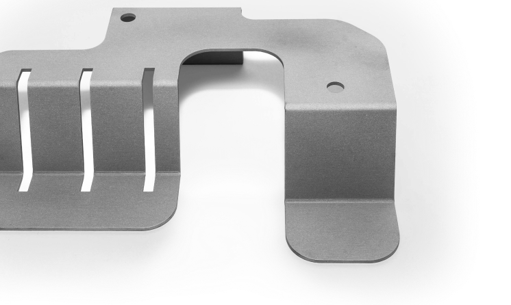
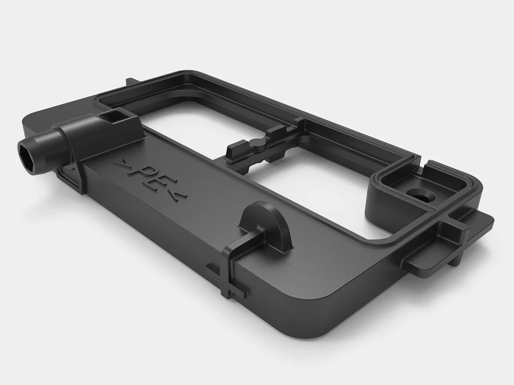
Process, material, finish and inspection decisions connected

Shenzhen, China

A practical manufacturing partner connecting process, materials, applications and review.

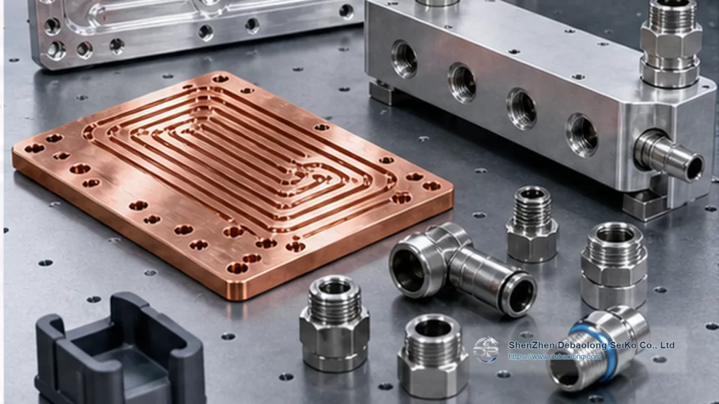
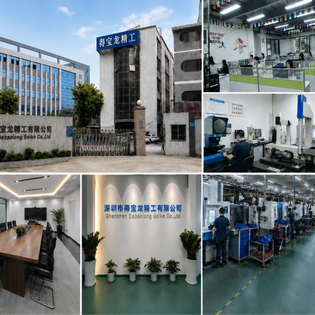
The factory collage shows building, workshop and manufacturing context.

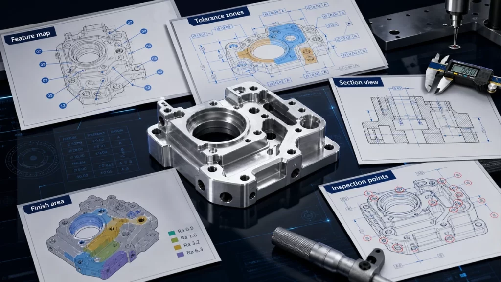
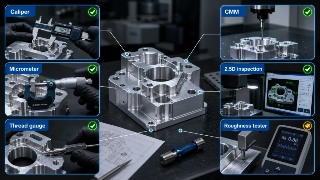
An illustrative planning graphic connects critical features, manufacturing decisions and engineering review. It is not a production inspection record.

Use Contact for general conversation or Engineering Review for a project-specific brief.
ADDITIVE MANUFACTURING

3D printing, matched to your part.

Choose SLA, SLS, MJF, FDM or SLM from geometry, material behavior, surface expectations, functional intent and production stage.

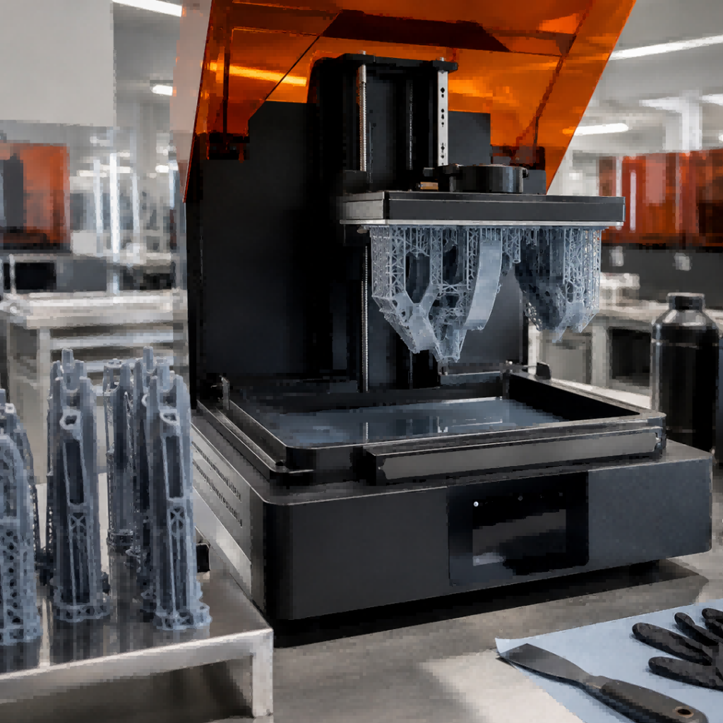
Industrial 3D printer with an orange protective cover printing a lattice part.
PROCESS SELECTION

Choose the build route

Five additive routes address different material, detail, support-removal and finishing requirements. Compare resin, polymer powder-bed, filament and metal powder-bed processes against the finished part you need.

Orange resin prototype with smooth surfaces and circular mounting features

SLA

Best for
Fine-detail and surface-critical resin prototypes.

Typical parts
Visual models, form/fit housings and appearance prototypes.

REVIEW FOCUS
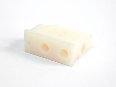
White polymer part with a circular flange and recessed geometric features

SLS

Best for
Complex nylon geometry without dedicated support structures.

Typical parts
Housings, clips, ducts and functional prototypes.

REVIEW FOCUS
Gray polymer housings and ribbed components with a powder-bed surface texture

MJF

Best for
Functional polymer parts with repeat-batch intent.

Typical parts
Nylon housings, fixtures and functional components.

REVIEW FOCUS
Black thermoplastic bracket with visible extrusion layers and mounting holes

FDM

Best for
Fast design iteration with thermoplastic prototypes.

Typical parts
Jigs, fixtures and larger form/fit models.

REVIEW FOCUS
Brush removing loose powder around metal additive parts on a build plate

SLM

Best for
Complex metal geometry that is difficult to make conventionally.

Typical parts
Lightweight structures and internal-geometry components.

REVIEW FOCUS
DESIGN REVIEW

Design for the build

Review the model for wall transitions, enclosed spaces, escape paths, support contact, orientation-sensitive features and interfaces that must fit after finishing.

Walls and transitions

Avoid treating every thin or thick section the same; local geometry and material behavior govern the review.

Support or powder access

SLA, FDM and SLM support contact differs from polymer powder-bed removal and trapped-volume concerns.

Orientation

Layer direction, visible surfaces and critical interfaces should be identified before the build is planned.

Assembly

Threads, inserts, mating faces and post-build operations need an explicit handoff.

MATERIAL AND USE

Match material to intended use

A visual model, fit-check part and functional bridge component may require different process and material decisions even when the CAD is identical.

  • State whether the part is visual, fit-check or functional
  • Identify heat, chemical, load or flexibility priorities
  • Separate short-term evaluation from repeat-production intent
Assorted white and gray 3D-printed plastic parts spread on a white surface, including lattice structures and mechanical components.
POST-PROCESSING

Plan the surface after the build

Support removal, cleaning, smoothing, dyeing, painting and assembly can change appearance, interfaces and inspection access.

Surface priority

Identify cosmetic faces and acceptable process texture.

Dimensional interfaces

Protect or rework mating faces only when the drawing and route call for it.

Color and coating

Define appearance references and compatibility before post-processing.

Assembly readiness

Confirm inserts, hardware and joining requirements after the build.

Assorted metallic engineering components with lattice and tubular designs arranged on a white background.
QUALITY EVIDENCE

Define inspection by intended use

Inspection should follow the function of the part: critical dimensions, fit, visible surfaces and post-processed interfaces rather than a generic additive checklist.

  • Mark critical dimensions and datums
  • Define fit or assembly checks
  • Agree visual evidence for customer-facing surfaces
APPLICATION EVIDENCE

See the manufacturing context

Debaolong manufacturing images show equipment, polymer geometries and complex structures. They support review, but do not replace the actual CAD.

PRACTICAL QUESTIONS

Questions to resolve before release

These are review prompts, not universal process promises. The actual drawing and requirement remain authoritative.

Which process should start the review?

Begin with part intent, material behavior and required surface; do not select only from appearance.

Sometimes, but production stage, repeatability and finishing expectations must be stated explicitly.

Quantity, material priorities, visible surfaces, critical dimensions, post-processing and assembly context.

ADDITIVE DECISION MAP

Compare five build routes

The process name is only the start. Geometry, support or powder access, surface intent and functional evidence determine the useful route.

Compare all four columns. On narrow screens, swipe across the table or focus it and use the arrow keys.

RouteGeometry reviewMaterial / evidencePost-build handoff
SLASupport contact, thin detail and enclosed resin pathsResin behavior and visible-surface referenceSupport removal, cleaning and cosmetic review
SLSPowder escape, wall transitions and nestingPowder-bed polymer behavior and functional contextDepowdering, dye or finish and interface checks
MJFPacking, powder access and repeat geometryPowder-bed polymer choice and repeat-part evidenceCleaning, color and dimensional interface review
FDMBuild direction, support access and layer-sensitive featuresThermoplastic choice and prototype or functional intentSupport removal, surface expectation and fit review
SLMSupport access, powder escape, orientation and interface stockAluminum, stainless steel or titanium base family with project-specific grade confirmationSupport removal, heat treatment, machining, surface and inspection review
FILE-TO-BUILD HANDOFF

Make open decisions visible

A useful additive brief identifies the part purpose and the surfaces, features and interfaces that cannot be treated as generic.

Build orientation priorities

Mark surfaces where layer direction, support contact or appearance matters.

Trapped volume and access

Identify enclosed spaces, powder escape paths and cleaning access.

Interfaces after finishing

Call out threads, inserts, mating faces and any secondary operation.

Evidence for release

Define dimensions, fit checks and visible-surface evidence for the intended use.

RELATED MANUFACTURING

Continue the engineering review

Move between the capability, material, knowledge and project-review paths without repeating the page you just read.

REVIEW PACKAGE

Prepare the review package

Geometry and support

Compare enclosed spaces, unsupported surfaces, feature scale and support removal before selecting a route.

Material and use

Connect the polymer, resin or metal grade to load, temperature, flexibility, appearance and the intended evaluation.

Post-process plan

Define support removal, sanding, coating, inserts, threads and any customer-facing surface before release.

Inspection evidence

Mark critical datums, mating features and visible zones; agree the fit and surface evidence needed for the intended use.
START WITH THE PART

Bring the drawing and decisions together.

Share CAD, quantity, material, finish and inspection requirements so the route can be reviewed against the actual part.