Why Tolerance Matters in Injection Molding
Dimensional accuracy is a core part of injection molded part design. If tolerance is not considered early, a molded part may assemble poorly, lose function, show warpage, or require expensive tooling and process changes after the design has already been released. Tight tolerances are especially important for complex plastic parts with mating features, seals, snap fits, inserts, moving interfaces, or assemblies that combine plastic and metal.
A practical reference for general injection molding tolerance is about +/-0.1 mm. Very tight plastic tolerances may approach about +/-0.025 mm, but those values should be treated as engineering decisions rather than default drawing settings. Resin behavior, part size, wall thickness, geometry, tooling, cooling and process control all influence whether the tolerance can be held reliably.
Factors That Affect Injection Molded Part Tolerance
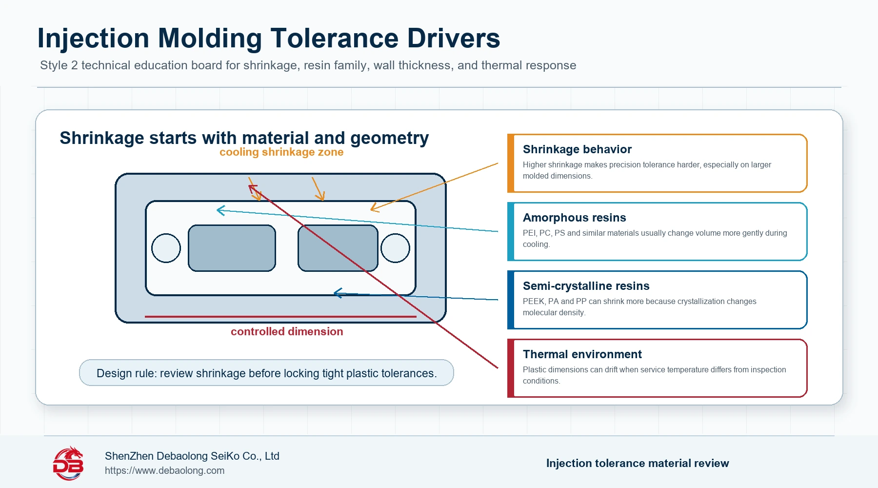
Shrinkage
Every molded plastic part shrinks as it cools. Different materials shrink at different rates, and higher shrinkage usually makes precision tolerance more difficult. Semi-crystalline materials such as PEEK, PA and PP often create more tolerance challenge than many amorphous materials because crystallization changes molecular density as the material cools. Amorphous materials such as PEI, PC and PS generally undergo less dramatic volume change during solidification.
The mold itself is machined larger than the target molded part so the final plastic component can contract toward the intended dimension. Because shrinkage is partly predictable, it can be built into tool design. However, small resin variations, wall thickness differences, process settings and part size can still affect final tolerance. Large parts magnify shrinkage variation, so a larger dimension often needs a wider realistic tolerance window than a small local feature.
How to Reduce Shrinkage Effects
Before locking a strict tolerance, review the selected plastic’s shrinkage rate and confirm whether the resin family fits the tolerance target. Shrinkage can be estimated, but it is not completely fixed; grade changes, fillers, moisture, cooling rate and process variation may change the result. A useful engineering habit is to separate critical dimensions from general dimensions, then discuss the critical ones with the molding team before tool release.
The source article gives an example that a 100 mm ABS part may have an approximate tolerance around +/-0.28 mm. The exact value depends on design and processing, but the lesson is durable: part-to-part repeatability can be consistent once the process is stable, yet the absolute tolerance target must respect material shrinkage.
Warpage
Warpage happens when different regions of the molded part cool and shrink at different rates. Uniform wall thickness helps the part shrink evenly. Uneven wall sections, thick bosses, abrupt transitions and heavy ribs can create localized cooling differences that lead to sink, internal stress and part distortion.
To reduce warpage, keep wall thickness as uniform as possible. If thickness changes cannot be avoided, use smooth or tapered transitions. As a practical rule, thickness changes should stay within about 15% of the nominal wall thickness when possible. Ribs and gussets usually provide stiffness more efficiently than simply adding wall thickness.
Recommended Wall Thickness Ranges
Recommended wall thickness depends on resin type and part function. The source article lists typical guidance such as ABS at about 1.1-3.5 mm, acetal at 0.7-3.0 mm, acrylic at 0.6-12 mm, liquid crystal polymer at 0.7-2.9 mm, long-fiber reinforced plastics at 1.9-27 mm, nylon at 0.7-2.9 mm, polycarbonate at 1.0-3.8 mm, polyester at 0.6-3.1 mm, polyethylene at 0.7-5.0 mm, polyphenylene sulfide at 0.5-4.5 mm, polypropylene at 0.88-3.8 mm, polystyrene at 0.88-3.8 mm and polyurethane at 2-19 mm.
These ranges are not a substitute for design review, but they show why tolerance cannot be separated from wall design. A part with a reasonable material but poor thickness transitions can still be difficult to hold accurately.
Thermal Expansion
Plastic parts may meet a tolerance in a controlled inspection room and still change dimension in the field. Many plastics have high coefficients of thermal expansion, so outdoor use, hot environments, cold environments, or assemblies with metal components can create dimensional drift over time. This is critical when plastic parts are combined with metal shafts, inserts, housings, fasteners or precision alignment features.
The best solution is material selection based on real service conditions. If the resin reacts unpredictably to the operating environment, tight tolerance may not remain stable. Materials such as ULTEM and PEEK generally tolerate heat better than ABS or PC, but the correct choice depends on the full part requirement, not only one property.
Part Design and Geometry
Part design is one of the strongest drivers of injection molding tolerance. Geometry, overall size, wall thickness, rib layout, bosses, undercuts and local feature density all influence how plastic flows, cools and shrinks. Thick sections may shrink differently through the section, while large dimensions accumulate more total shrinkage variation than smaller features.
Good tolerance design begins early in CAD. Identify the dimensions that truly require tight control, then design the surrounding geometry to support them. Keep walls uniform, avoid abrupt mass changes, use ribs or gussets for strength instead of thick walls, and avoid setting tight tolerances across large nonfunctional spans unless the application genuinely requires it.
Part Complexity, Flow and Mold Design
Complexity affects material flow, filling time, mold temperature and cooling management. Undercuts, side actions, deep ribs, thin flow paths and complex cavity layouts can make precision tolerance more difficult. The designer does not control every molding variable, but design choices strongly influence how stable the molding process can become.
If complexity is necessary, mold design must support it. Side actions, cooling strategy, mold-flow analysis and process windows should be reviewed before final tooling. Tracking injection pressure, resin viscosity, mold filling time, heating and cooling can help engineers adjust variables and reduce variation. Mold-flow analysis is especially useful for predicting shrinkage, warpage, filling risk and cooling imbalance.
Tooling and Process Control
The source article separates injection molding tooling into three common types. A single-cavity tool produces one part per shot. A multi-cavity tool produces multiple copies of the same part per shot. A family tool produces multiple different parts of an assembly in one shot. Each tooling strategy has tolerance implications.
Tool design, tool material and cavity count affect the ability to hold tight tolerance. More cavities usually require more careful cooling balance. If the tool cannot cool consistently and repeatably, shrinkage variation rises and tolerance becomes harder to control. Cavity layout, pressure distribution, temperature control and tool stiffness all matter.
Process control helps reduce variation after tooling is built. Temperature and pressure sensors can provide real-time feedback during development and production. When unacceptable variation appears, process parameters can be adjusted more quickly. A stable mold, good cooling design and controlled process window make tight tolerance more realistic.
Do All Molded Parts Need Tight Tolerance?
Before manufacturing, the most important question is whether the part actually needs strict tolerance. Designers may apply one tight tolerance value broadly in CAD, but many surfaces do not affect fit, function or quality. Tightening every dimension increases tooling, development, inspection and production cost.
For practical manufacturing, keep tight tolerance on functional interfaces: assembly fits, sealing surfaces, snap-fit engagement areas, insert locations, bearing surfaces, alignment datums and features that directly affect performance. Use reasonable general tolerances for noncritical geometry.
How DEBAOLONG Reviews Injection Molding Tolerance
DEBAOLONG reviews injection molded part tolerance together with resin choice, wall thickness, part size, ribs, bosses, undercuts, tool construction, cooling strategy and inspection access. Early DFM review helps identify which dimensions require strict control and which can remain practical.
Related DEBAOLONG resources include the injection molding materials selection guide, the injection molding defects troubleshooting guide, and the DFM prototyping guide. Together, they connect material behavior, geometry, process risk and tolerance planning.
Conclusion
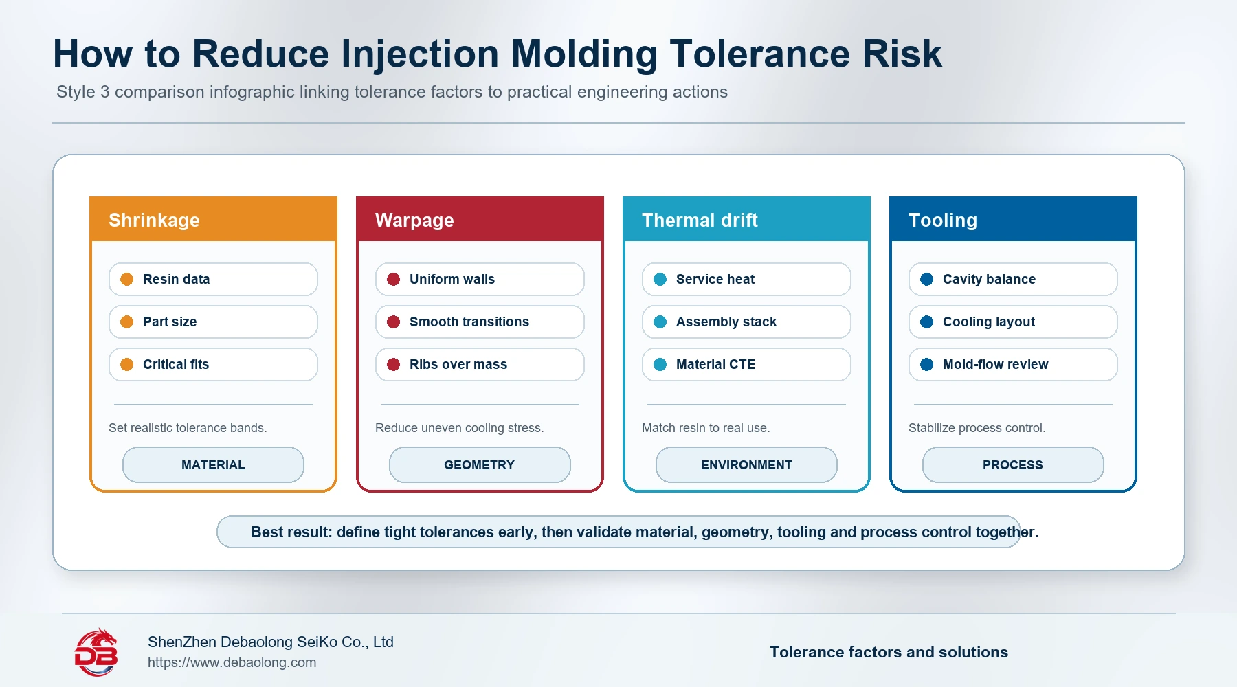
Injection molding tolerance is controlled by more than mold machining accuracy. Material shrinkage, warpage, thermal expansion, geometry, part size, tooling layout, cavity count and process stability all work together. The best engineering approach is to define critical tolerances early, design geometry that supports stable molding, select material for the real operating environment and use tooling and process controls that make repeatable production possible.
Related Engineering Resources