Improve 3D printed part strength with better geometry, fillets, ribs, infill, build orientation, shell thickness, annealing, plating, resin coating and reinforcement.
This expanded DEBAOLONG guide follows the source article’s engineering flow while rewriting the material in independent English for manufacturing buyers, designers and engineering teams. It focuses on practical decisions: when the process is useful, where risk appears, what details should be specified, and how to connect prototype evidence with production planning.
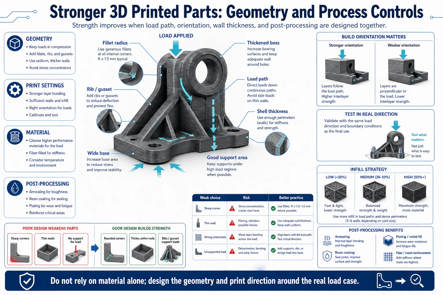
Part Geometry Controls Strength
The source article begins with geometry because printed strength is not only a material issue. Sharp corners, thin walls, unsupported features and poor load paths can weaken a part before printing begins.
Fillets, chamfers, ribs and gussets help distribute stress and reduce crack initiation. These changes are usually more reliable than simply choosing a stronger material after the design is already weak.
Printed strength begins with load path. A weak corner, thin transition or unsupported wall can fail even when the selected material has strong datasheet values.
Designers should identify compression, tension, bending and impact loads before adding material. Reinforcement works best when it follows the real force direction.
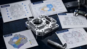
In practice, this section should be checked against the drawing, CAD model, quantity and inspection requirement before the design is released. The same guideline can lead to different decisions for a visual prototype, a functional test part, a bridge-production batch and a repeat production component.
Fillets, Chamfers, Ribs and Gussets
Fillets and chamfers reduce stress concentration at corners and transitions. Ribs and gussets add stiffness without turning the part into a thick solid block that may warp or print poorly.
The best reinforcement follows the expected load path. Decorative ribs or random thickness increases may add print time without improving functional strength.
Fillets and chamfers reduce stress concentration and make transitions easier to print. Ribs and gussets add stiffness without creating a thick solid block that traps heat or increases warpage.
Reinforcement should have enough root radius and wall balance. Random ribs may add print time while doing little for the expected failure mode.
In practice, this section should be checked against the drawing, CAD model, quantity and inspection requirement before the design is released. The same guideline can lead to different decisions for a visual prototype, a functional test part, a bridge-production batch and a repeat production component.
Print Settings: Infill, Orientation and Shell Thickness
Infill percentage, infill pattern, build orientation and outer shell thickness all influence printed strength. A part loaded across weak layer lines may fail much earlier than the same geometry printed in a better orientation.
Higher infill is not always the answer. Shell thickness, local reinforcement and orientation can matter more than filling the entire part with material.
Build orientation can dominate strength because layer bonding is usually weaker than strength within a layer. A loaded hook, hinge or bracket should be oriented around the expected load.
Higher infill can help, but shell thickness, local bosses, fiber direction, lattice layout and support strategy often matter more than simply increasing percentage everywhere.
In practice, this section should be checked against the drawing, CAD model, quantity and inspection requirement before the design is released. The same guideline can lead to different decisions for a visual prototype, a functional test part, a bridge-production batch and a repeat production component.
Post-Processing for Stronger Printed Parts
Annealing, plating, resin coating and fiber reinforcement can improve specific properties when used correctly. Each method has trade-offs: annealing may change dimensions, coatings can add thickness, and reinforcement may complicate assembly.
Post-processing should be selected around the failure mode the team wants to reduce.
Annealing can improve selected thermoplastics but may change dimensions. Coatings and plating can improve surface or stiffness but add thickness that affects fits.
Post-processing should be chosen after the likely failure mode is known: crack initiation, layer separation, wear, creep, moisture exposure or surface damage.
In practice, this section should be checked against the drawing, CAD model, quantity and inspection requirement before the design is released. The same guideline can lead to different decisions for a visual prototype, a functional test part, a bridge-production batch and a repeat production component.
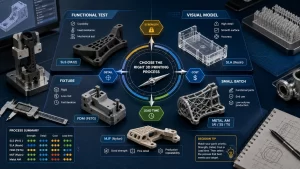
DEBAOLONG Strength Review
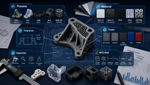
DEBAOLONG reviews 3D printed parts for load direction, wall thickness, local reinforcement, orientation, material and post-processing before recommending a manufacturing route. If the part needs final-use strength, CNC machining, molding or another process may be a better next step.
DEBAOLONG checks whether a printed part should remain printed, become a machined prototype, or move toward molding or casting for production strength.
The review connects geometry, orientation, material, finishing, tolerance and inspection so the part is not judged by appearance alone.
In practice, this section should be checked against the drawing, CAD model, quantity and inspection requirement before the design is released. The same guideline can lead to different decisions for a visual prototype, a functional test part, a bridge-production batch and a repeat production component.
Practical Release Checklist
Before publishing a design for quotation or production, confirm the intended application, annual or batch quantity, material requirement, critical dimensions, cosmetic expectations, operating environment, inspection method and acceptable lead time. These inputs make the manufacturing recommendation more reliable and prevent the article’s guidance from being used as a generic rule without project context.
For related planning, review the DEBAOLONG Manufacturing Engineering Knowledge Center, compare major manufacturing process options, or use DFM for prototyping before production release.
FAQ
How should engineers use this how to make stronger 3d printed parts: geometry, settings and post-processing guide?
Use it as a decision checklist before quoting, prototyping or production release. The most useful result is a clearer specification, not just a faster order.
When should the design be reviewed by a manufacturer?
Review should happen before the design is treated as frozen, especially when material, tolerance, surface finish, wall thickness, cleaning, assembly or production quantity affects the result.
Can DEBAOLONG help turn the review into a production-ready plan?
Yes. DEBAOLONG can review geometry, material selection, tolerance, finish, inspection and process choice so the project moves from prototype evidence toward a controlled manufacturing route.
Related Engineering Resources