Selecting SLS for nylon parts gives designers far more geometric freedom than most conventional polymer processes, but that freedom only works when the part is designed for real powder-bed behavior. The process can build complex enclosed forms, living features and low-volume production parts, yet it also introduces risks around trapped powder, shrinkage, unsupported slender geometry and fit after post-processing.
That is why a good SLS design review goes beyond whether a feature can print. It asks whether the part can be cleaned, measured, assembled and used without distortion or unexpected weakness. The best results come from treating SLS as a real engineering production method rather than as a generic prototype shortcut.
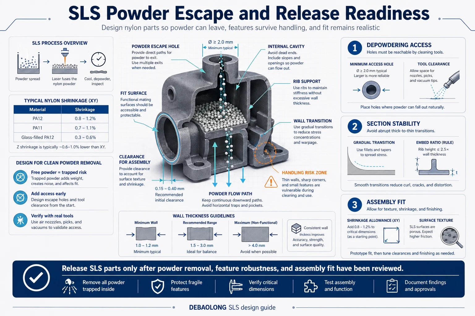
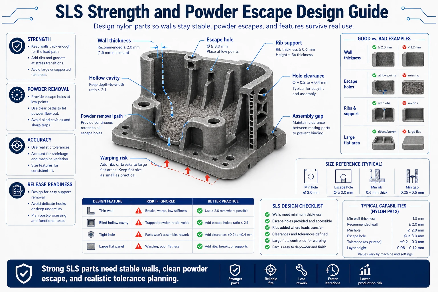
1. Start with wall thickness and section stability
Wall thickness is the first structural choice in SLS. Very thin sections may appear acceptable in CAD, yet they can distort during cooling, chip during blasting or fail during handling. For load-bearing features, it is usually better to create short reinforced sections, blend transitions and local ribs than to rely on long thin unsupported walls. Stable section design also improves repeatability across multiple builds, which matters once the project moves beyond one-off samples.
Designers should also avoid abrupt thick-to-thin transitions where possible. Those transitions collect thermal stress and can produce uneven shrinkage. When a change in section is unavoidable, tapering and radiusing usually produce better results than sudden steps.
2. Design every enclosed volume for powder escape
One of the main advantages of SLS is that support structures are not required in the same way as in many other additive processes. The tradeoff is that unused powder remains around and inside the part until it is removed. Hollow parts, ducts, channels and internal cavities therefore need deliberate powder-removal planning. Escape holes should be placed where cleaning tools and media can actually reach them, not just where they look neat in CAD.
Internal passages also need realistic size choices. A channel that is theoretically present in the model may still be difficult to depowder, inspect or clean consistently. If the feature has to carry air, liquid or cable routing in the final product, engineers should verify that the pathway remains usable after printing and finishing rather than assuming the digital geometry will survive unchanged.
3. Size holes, channels and mating features for real post-processing
SLS can create holes and internal pathways effectively, but those features are affected by surface texture, powder removal access and dimensional variation. When the part contains mating tabs, rotating joints, snap features or inserted components, a nominal zero-clearance design nearly always causes trouble later. Practical assembly allowance is part of the design, not a correction after the fact.
This is especially important when the part has multiple mating faces or when it must interface with machined or molded components. In those cases, it often helps to isolate one or two critical fit surfaces and allow the rest of the geometry to stay under a more forgiving baseline tolerance.
4. Protect fine details and slender structures
Text, small hooks, thin fingers, pins and delicate decorative details often pass a basic printability check but fail under blasting, handling or first use. Engineers should distinguish between cosmetic details and truly functional small features. Functional fine features should be shortened, thickened, radiused or anchored more effectively wherever possible.
Long narrow cantilevers and tall unsupported features deserve special review. A part may leave the machine successfully and still arrive warped or damaged because the geometry was too delicate for depowdering and transport. For functional parts, robustness during the full manufacturing chain matters more than whether a single sample can be built once.
5. Account for shrinkage, tolerances and production intent
SLS introduces dimensional variation that needs to be anticipated early, especially on larger parts or assemblies. Shrink behavior does not mean the process is inaccurate; it means the design should focus precision where it matters most. Large flat areas, critical assembly interfaces and full-length dimensions often need more attention than local decorative geometry.
At DEBAOLONG, we recommend judging SLS parts against three practical questions: can powder leave the geometry, will the feature survive handling, and will the final printed part still answer the intended engineering requirement? That mindset leads to stronger nylon parts, better assembly outcomes and more reliable low-volume production.
For related additive guidance, review SLS post-processing methods, compare with PolyJet design rules, and see CNC machining vs 3D printing.
Production release review for SLS parts
Before release, teams should confirm that the model has realistic wall transitions, accessible escape holes and fit surfaces that are dimensioned according to how the part will actually be assembled. This final review is where many hidden issues can be removed cheaply, before the first build is launched.
It is also a good stage to define what will be visually inspected, what will be measured and what level of cosmetic variation is acceptable. That clarity makes short-run production much more repeatable.
FAQ
Why do SLS parts need powder escape features?
Because trapped powder can add weight, block functionality and make post-processing or assembly difficult.
Are thin walls always bad in SLS?
No, but thin unsupported features need more caution and often benefit from reinforcement or shorter spans.
What causes poor fit in SLS assemblies?
Surface texture, shrinkage and unrealistic clearance assumptions are the most common causes.
Related Engineering Resources