A practical engineering guide to additive manufacturing in electronics, covering rapid prototyping, customization, experimental materials, surface quality, lightweight design and production support.
This expanded DEBAOLONG guide follows the source article’s engineering flow while rewriting the material in independent English for manufacturing buyers, designers and engineering teams. It focuses on practical decisions: when the process is useful, where risk appears, what details should be specified, and how to connect prototype evidence with production planning.
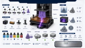
When Electronics Teams Should Consider 3D Printing
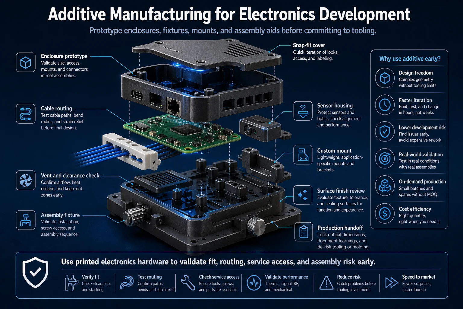
Electronics projects often move quickly from circuit layout to enclosure, connector, fixture and assembly review. Additive manufacturing is useful when teams need physical feedback before hard tooling, machining or molded production is justified.
The strongest use cases include enclosure prototypes, cable routing samples, sensor housings, custom mounts, test fixtures and assembly aids. The printed part should always be tied to a specific engineering question rather than treated as a generic sample.
Use the printed part to answer a defined question: board clearance, connector access, cable routing, button feel, fixture repeatability or assembly sequence. A prototype that is not tied to a decision can create visual confidence without reducing production risk.
Electronics parts also need early review for heat, flame behavior, electrostatic sensitivity, insert strategy and enclosure stiffness. Those requirements decide whether the printed part is only a development aid or a realistic bridge toward CNC machining, sheet metal or molding.
In practice, this section should be checked against the drawing, CAD model, quantity and inspection requirement before the design is released. The same guideline can lead to different decisions for a visual prototype, a functional test part, a bridge-production batch and a repeat production component.
On-Demand Production and Faster Prototyping
For electronics teams, on-demand printing reduces waiting time during development. A design can be printed, checked against the PCB or assembly, revised and tested again before production tooling begins.
This supports faster innovation because the team can test more enclosure shapes, board supports, button layouts, mounting points and connector openings while the design is still flexible.
Short build cycles are especially valuable when the PCB outline, connector position or display opening is still changing. Printing lets mechanical and electrical teams test the same revision quickly instead of waiting for a full production route.
For small batches, on-demand production can also support test jigs, programming fixtures, protective covers and low-volume accessories. The design still needs version control, clear material notes and inspection expectations so each iteration teaches something useful.
In practice, this section should be checked against the drawing, CAD model, quantity and inspection requirement before the design is released. The same guideline can lead to different decisions for a visual prototype, a functional test part, a bridge-production batch and a repeat production component.
Innovation, Customization and Experimental Materials
Additive manufacturing gives engineers more room to explore custom geometry, low-volume variants and experimental material ideas. It can support housings with unusual shapes, lightweight supports, conformal fixtures and short-run accessories.
However, experimental materials must be reviewed carefully. Heat, flame behavior, electrical insulation, surface finish and long-term stability matter in electronics applications.
Customization is useful for device variants, cable exits, mounting layouts and region-specific accessory designs. Additive manufacturing can support these differences without new tooling, but every variant should still be checked against fastening, assembly and service requirements.
Experimental materials should be used carefully. A material that prints well may not survive heat cycling, cleaning chemicals, screw loads or repeated handling inside an electronics program.
In practice, this section should be checked against the drawing, CAD model, quantity and inspection requirement before the design is released. The same guideline can lead to different decisions for a visual prototype, a functional test part, a bridge-production batch and a repeat production component.
Surface Finish, Lightweight Design and Waste Reduction
The source article also emphasizes surface quality, lightweight design and lower material waste. Printed parts can reduce material removal compared with machining, and some processes can produce acceptable surfaces for internal device prototypes or fixtures.
Designers should still plan post-processing when cosmetic appearance, tactile quality or assembly interfaces matter. A printed electronics housing may need sanding, coating, inserts or machining on critical features.
Surface finish affects more than appearance. It can change button travel, gasket contact, label adhesion, dirt retention and how a customer-facing enclosure feels in the hand.
Lightweight design should protect stiffness around fasteners, clips and PCB supports. Removing material is only valuable when the remaining geometry still controls vibration, assembly force and impact risk.
In practice, this section should be checked against the drawing, CAD model, quantity and inspection requirement before the design is released. The same guideline can lead to different decisions for a visual prototype, a functional test part, a bridge-production batch and a repeat production component.
Engineering Review for Electronics Applications
DEBAOLONG reviews printed electronics parts for board clearance, fastening strategy, connector access, thermal exposure, material selection and production intent. This keeps prototypes connected to manufacturing decisions and prevents late redesign when the project moves toward CNC machining, molding or sheet metal fabrication.
A practical release review should include PCB keep-out zones, screw boss dimensions, insert pull-out risk, connector tolerance stack-up, thermal exposure and the planned transition to production manufacturing.
DEBAOLONG can use the printed prototype as evidence, but the final process choice should be based on functional duty, quantity, material behavior and the customer-facing finish requirement.
In practice, this section should be checked against the drawing, CAD model, quantity and inspection requirement before the design is released. The same guideline can lead to different decisions for a visual prototype, a functional test part, a bridge-production batch and a repeat production component.
Practical Release Checklist
Before publishing a design for quotation or production, confirm the intended application, annual or batch quantity, material requirement, critical dimensions, cosmetic expectations, operating environment, inspection method and acceptable lead time. These inputs make the manufacturing recommendation more reliable and prevent the article’s guidance from being used as a generic rule without project context.
For related planning, review the DEBAOLONG Manufacturing Engineering Knowledge Center, compare major manufacturing process options, or use DFM for prototyping before production release.
FAQ
How should engineers use this additive manufacturing in electronics: prototypes, custom parts and production support guide?
Use it as a decision checklist before quoting, prototyping or production release. The most useful result is a clearer specification, not just a faster order.
When should the design be reviewed by a manufacturer?
Review should happen before the design is treated as frozen, especially when material, tolerance, surface finish, wall thickness, cleaning, assembly or production quantity affects the result.
Can DEBAOLONG help turn the review into a production-ready plan?
Yes. DEBAOLONG can review geometry, material selection, tolerance, finish, inspection and process choice so the project moves from prototype evidence toward a controlled manufacturing route.
Related Engineering Resources