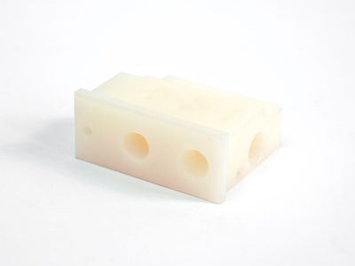
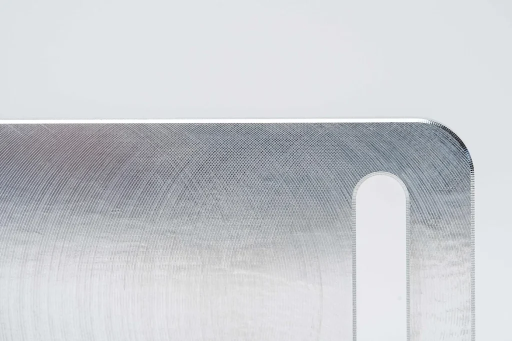



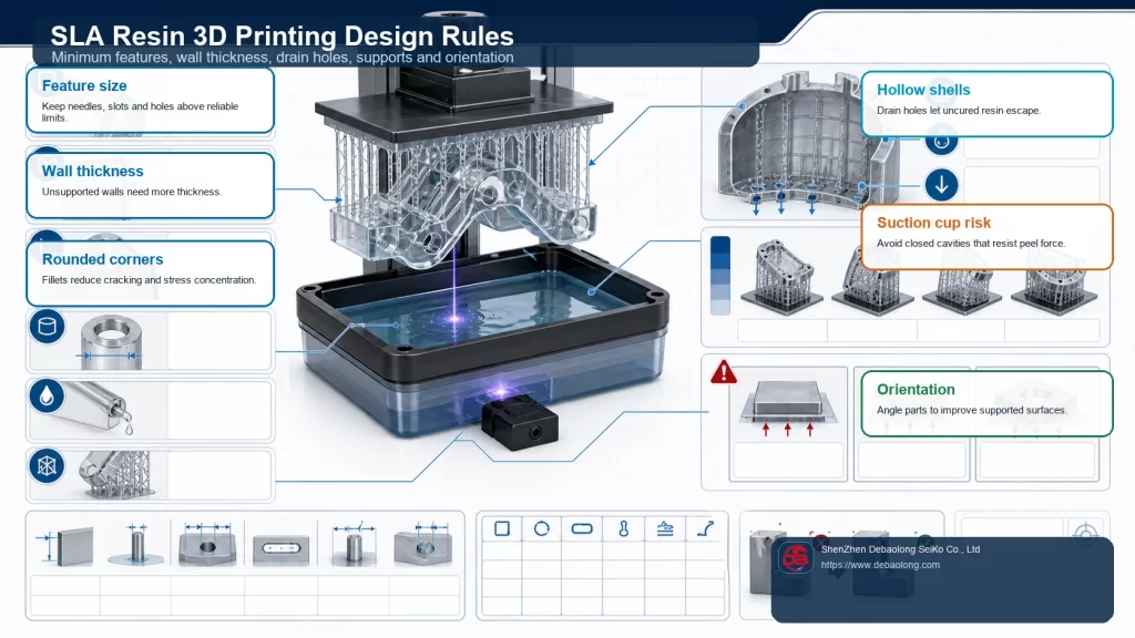
SLA 3D printing, also known as stereolithography, is a resin additive manufacturing process that uses focused ultraviolet light to cure liquid photopolymer resin layer by layer. Because the process can produce fine detail and smooth surfaces, it is often selected for prototypes, appearance models, small functional parts, and parts with engraved or embossed features.
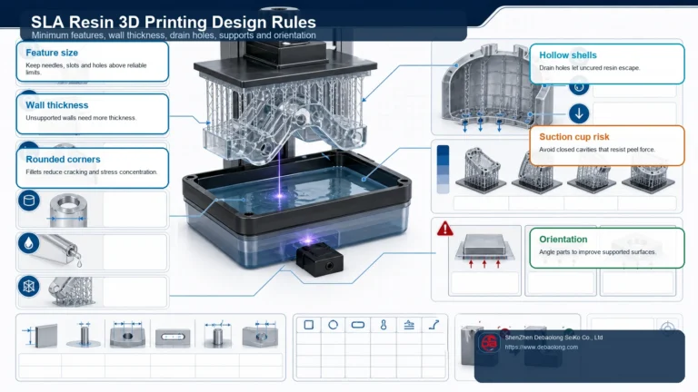
Good SLA results still depend heavily on CAD design. Wall thickness, minimum holes, unsupported overhangs, assembly clearance, and raised or recessed details all need to respect the way resin cures, drains, and separates from supports. Use this checklist to define which features must be reviewed with the chosen resin, printing equipment and post-curing process before release.
What SLA 3D Printing Means for Part Design
In SLA printing, each layer is formed as ultraviolet light cures the cross-section of the model inside a resin vat. After one layer is cured, the build process repeats until the part is complete. This method can create fine geometry, but uncured resin, support marks, post-curing, and part orientation can all affect the final result.
For designers, that means SLA should not be treated as a process with unlimited feature freedom. Even when a CAD model looks correct on screen, features that are too thin, too small, too close together, or too difficult to drain may become fragile, blocked, fused, or hard to finish after printing.
Build Size, Minimum Feature Size, and Tolerance
Build envelope, printable detail and dimensional acceptance are different questions. Confirm the available equipment and resin first; then identify small features, datum surfaces and critical fits on the drawing. A machine’s layer setting does not establish the finished part’s dimensional tolerance.
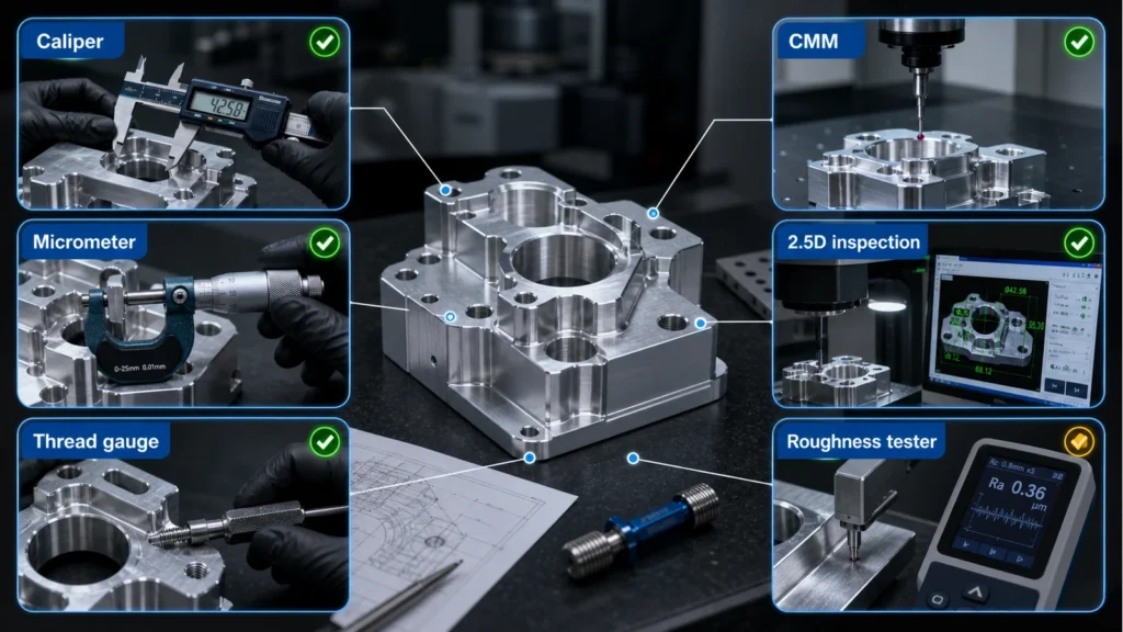
Request feature-specific acceptance limits for the finished, post-cured part. Include its overall size, orientation, support contact areas and inspection method. Where a fit is critical, review a representative test feature or first article before committing to the complete assembly.
Wall Thickness
A wall joined to surrounding geometry behaves differently from a tall, free-standing wall. Review wall height, unsupported span and handling loads together, not thickness alone. Thin sections may distort during separation from the vat, washing, support removal or post-curing.
Mark fragile walls and ribs in the CAD review. Discuss additional thickness, local support or a change of orientation where needed, while checking that the revised geometry still drains and can be cleaned. Use the selected supplier’s resin-and-equipment guidance rather than one universal minimum.
Overhangs and Support Planning
Review support locations before accepting an orientation. A surface that must remain cosmetic, seal against another part or locate an assembly may be unsuitable for support contact. Automatic support generation is a starting point, not proof that the finished surface will meet the drawing.
For an unsupported feature, identify its length, cross-section and angle relative to the build platform. Agree whether to reorient it, add removable supports or divide the model into separately assembled parts. Include access for support removal and the resulting surface condition in the review.
Hole Size and Long Channels
Distinguish a functional hole from a drain opening. Small openings can narrow or close during printing, while long channels can retain uncured resin. Review channel length, bends, orientation and cleaning access together with diameter.
Provide accessible drainage and cleaning paths for cavities. For a critical bore, specify the required finished dimension and discuss whether post-processing and inspection are feasible. Do not assume that an opening visible in CAD will be open, clean and dimensionally acceptable after curing.
Assembly Clearance
Separate parts assembled after printing and print-in-place moving components require different reviews. Specify the mating geometry, intended motion and acceptable play. Allow for both mating parts’ variation, support marks and any coating or finishing allowance.
Confirm the gap with the selected resin and orientation. For a critical sliding or rotating joint, use a representative fit check after washing and post-curing; do not rely on a generic clearance value to guarantee motion.
Embossed and Engraved Details
Check the stroke width, height or depth, spacing and orientation of text or markings. A raised feature may be fragile, and a recessed feature may retain resin or become less distinct after finishing.
Review a sample at the intended reading distance where legibility matters. Include paint, polishing and other post-processing in that check, and keep critical identification away from support-contact areas where possible.
Practical SLA Design Checklist
| Feature | Information to provide | Acceptance check |
|---|---|---|
| Walls and ribs | Height, span, support and handling requirements | Shape and integrity after cleaning and curing |
| Holes and channels | Function, flow path and cleaning access | Open passage and specified finished dimensions |
| Mating parts | Required motion, fit and surface finish | Fit check on representative finished geometry |
| Cosmetic faces | Visible surfaces and allowable support contact | Agreed appearance after support removal |
| Text and markings | Stroke geometry and reading requirement | Legibility after the intended finishing process |
For an example of why the test conditions matter, the Formlabs Form 4 design guide identifies the printer, resin and layer setting used for its recommendations. Those supplier-specific results are not universal SLA limits or a Debaolong manufacturing guarantee.
When to Use SLA for Prototyping
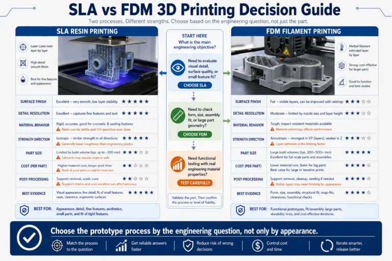
SLA is a strong choice when the project requires fine surface detail, clean appearance, small text, complex shapes, or quick design validation. It is especially useful for appearance prototypes, ergonomic models, transparent or special resin parts, and components that need visual review before production tooling.
For projects that require stronger engineering plastics, high-temperature performance, or production-grade mechanical behavior, compare SLA with other 3D printing material options and production processes. If the part will later move to machining or molding, early DFM review can help avoid redesign work.
How DEBAOLONG Supports Resin 3D Printed Parts
DEBAOLONG supports prototype and low-volume manufacturing projects across 3D printing, CNC machining, sheet metal fabrication, injection molding, and related manufacturing services. For SLA-style resin parts, our team can help review feature size, wall thickness, clearance, appearance requirements, and the best path from prototype to production.
FAQ
Can one minimum wall thickness be used for all SLA parts?
No. Review the wall’s height, support and handling requirements with the chosen resin, equipment and finishing process. Agree the finished part’s acceptance criteria before release.
Can SLA print functional assemblies?
It can be considered for suitable assemblies, but motion and fit need a defined clearance and a finished-part check. A printed gap alone does not prove that a mechanism will move reliably.
How should small holes and channels be reviewed?
Specify their function, length, bends and required finished dimensions. Confirm drainage, cleaning access and an inspection method appropriate to the feature.
Continue with the SLA capability or the focused support and drainage guide. Include cosmetic faces, cleaning access and finished-part acceptance criteria when you submit CAD for review.