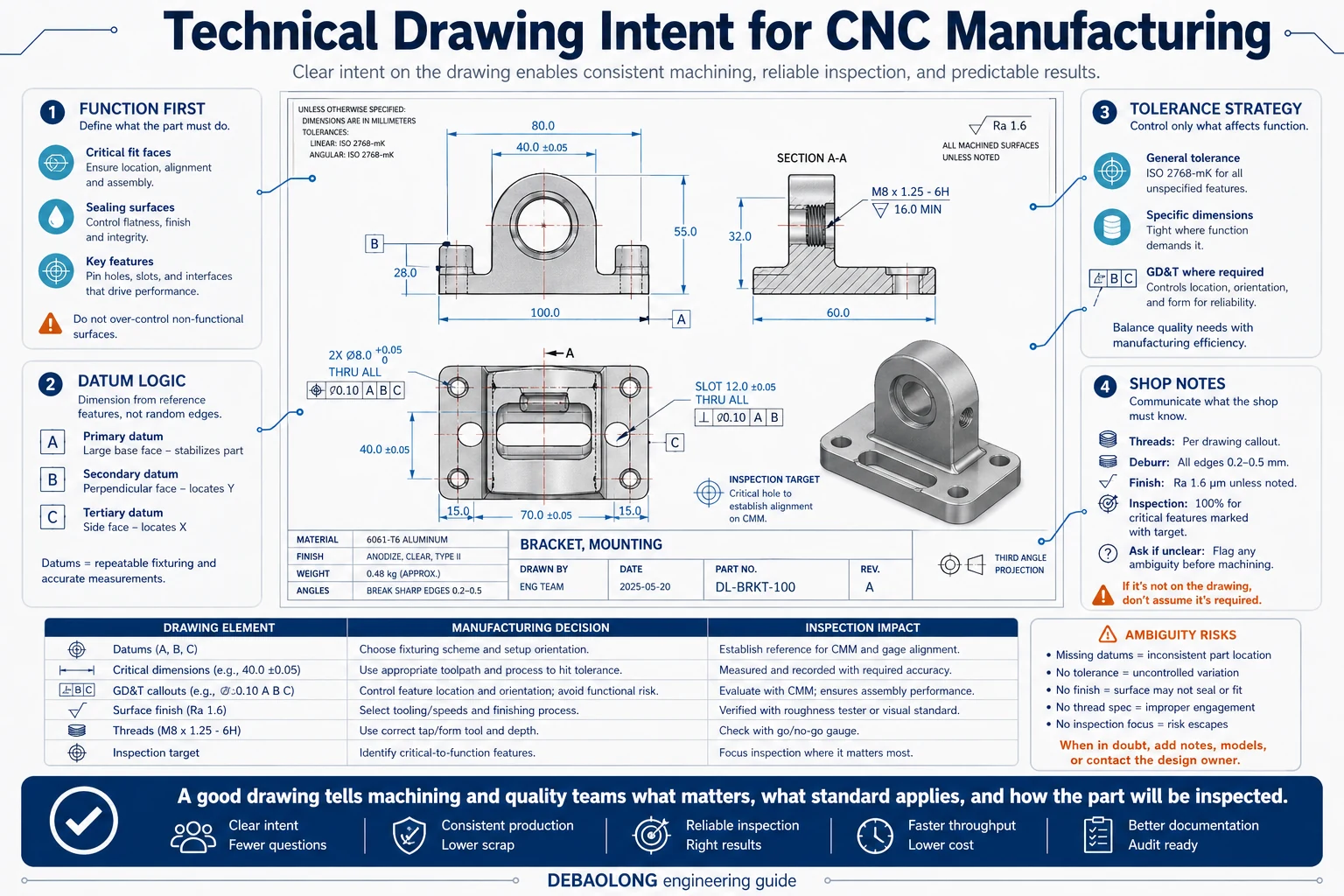
Even in a model-based workflow, a strong technical drawing remains one of the best ways to communicate manufacturing and inspection intent. The drawing is where the engineer tells the machining and quality teams what matters, what can follow a general standard and what absolutely must not be interpreted loosely.
Weak drawings create expensive ambiguity. Poor datum structure, excessive dimensions, incomplete thread callouts and vague notes all slow the quote, increase setup assumptions and make inspection more difficult. A clear drawing is therefore not paperwork. It is part of the manufacturing strategy.
1. Use the drawing to communicate function, not to duplicate CAD
A drawing should not simply repeat every detail already visible in the 3D model. Its job is to identify datums, critical dimensions, key views, surface expectations and any note that changes how the part should be made or checked. If the drawing adds pages of visual clutter without clarifying manufacturing intent, it is not helping.
That is why the best drawings tend to be selective. They show the views that matter, dimension from logical reference features and emphasize the geometry that drives fit, function or quality control.
2. Build the drawing in a logical sequence
A reliable drawing workflow starts with the right template, title block and unit system. From there, the engineer chooses principal orthographic views, then adds section or detail views only where they reveal information the standard views cannot show clearly. An isometric view often helps readability, but it should support the drawing rather than replace proper dimensioning.
Once the view structure is established, dimensions should be added from chosen datums instead of being chained randomly around the page. This keeps inspection logic cleaner and reduces the risk that the same feature will be interpreted differently by different people.
3. Make dimensions, notes and tolerances work together
A common mistake is to dimension too much while explaining too little. General tolerances can be defined in the title block or general note structure, while critical features such as sealing faces, bearing fits, threads or datums should carry the specific tolerance or specification they need. This division keeps the drawing readable and helps the supplier focus process control where it matters.
Notes should be equally deliberate. Thread definitions, finish callouts, deburring expectations, inspection requirements and special handling instructions should all appear where they can be understood quickly. The drawing should not force the shop to guess which standard was intended.
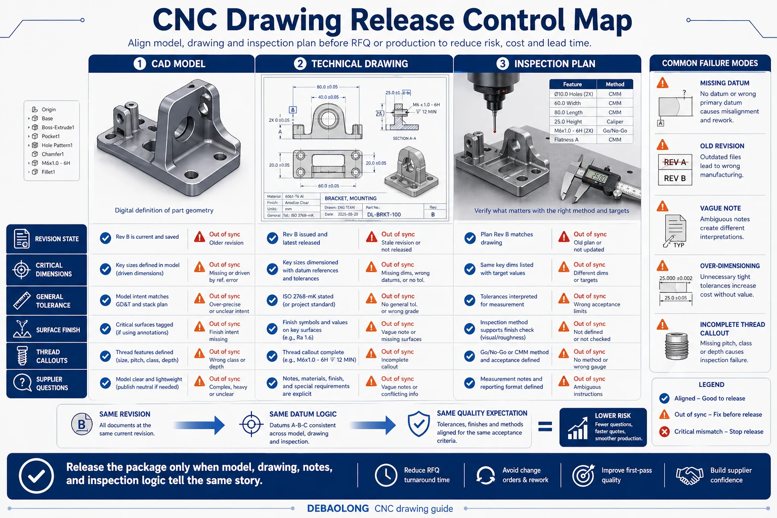
4. Revision control and consistency are part of quality
A technically correct drawing still causes problems if the revision, CAD model and notes are out of sync. Every release should confirm that the title block, revision state, view logic and dimension set all match the current design. This is especially important when multiple stakeholders are using the file for quoting, machining and inspection at different times.
At DEBAOLONG, we recommend reviewing drawings with one simple question in mind: would a machining and quality team that has never seen this part before understand exactly what matters after a short read? If the answer is no, the drawing still needs work.
For related precision communication, review CNC tolerance planning, compare with surface finish control, and read how DFM improves prototype success.
Run a release checklist before sending the drawing out
A final release checklist catches many of the mistakes that create quoting delays and shop-floor questions later. Revision mismatch, incomplete notes, missing datums and unclear general tolerances are all easier to fix before the RFQ or purchase order is sent than after production has started.
That checklist is especially useful when multiple designers or suppliers are involved, because it keeps the drawing package consistent from project to project.
FAQ
Do machinists still need drawings if a 3D model is provided?
In many precision projects, yes, because drawings clarify datums, tolerance priorities and inspection logic.
What is a common technical drawing mistake?
Over-dimensioning and weak datum structure are among the most common causes of confusion and cost.
Should every feature have a special tolerance?
No. Most parts benefit from a general baseline with special tolerances only on truly critical geometry.
Related Engineering Resources