FDM is one of the most flexible and accessible additive processes, but it also punishes weak geometry decisions quickly. A part that looks clean in CAD may warp on the bed, split along layer lines or require too much support to be economical if the design ignores orientation, thermal behavior and the true service load.
The most successful FDM parts are planned around the physical realities of extrusion. Engineers need to think about the nozzle path, wall build-up, bridge limits, overhangs, cooling behavior and assembly allowance before the print is started. When those decisions are left to the slicer alone, quality becomes inconsistent.
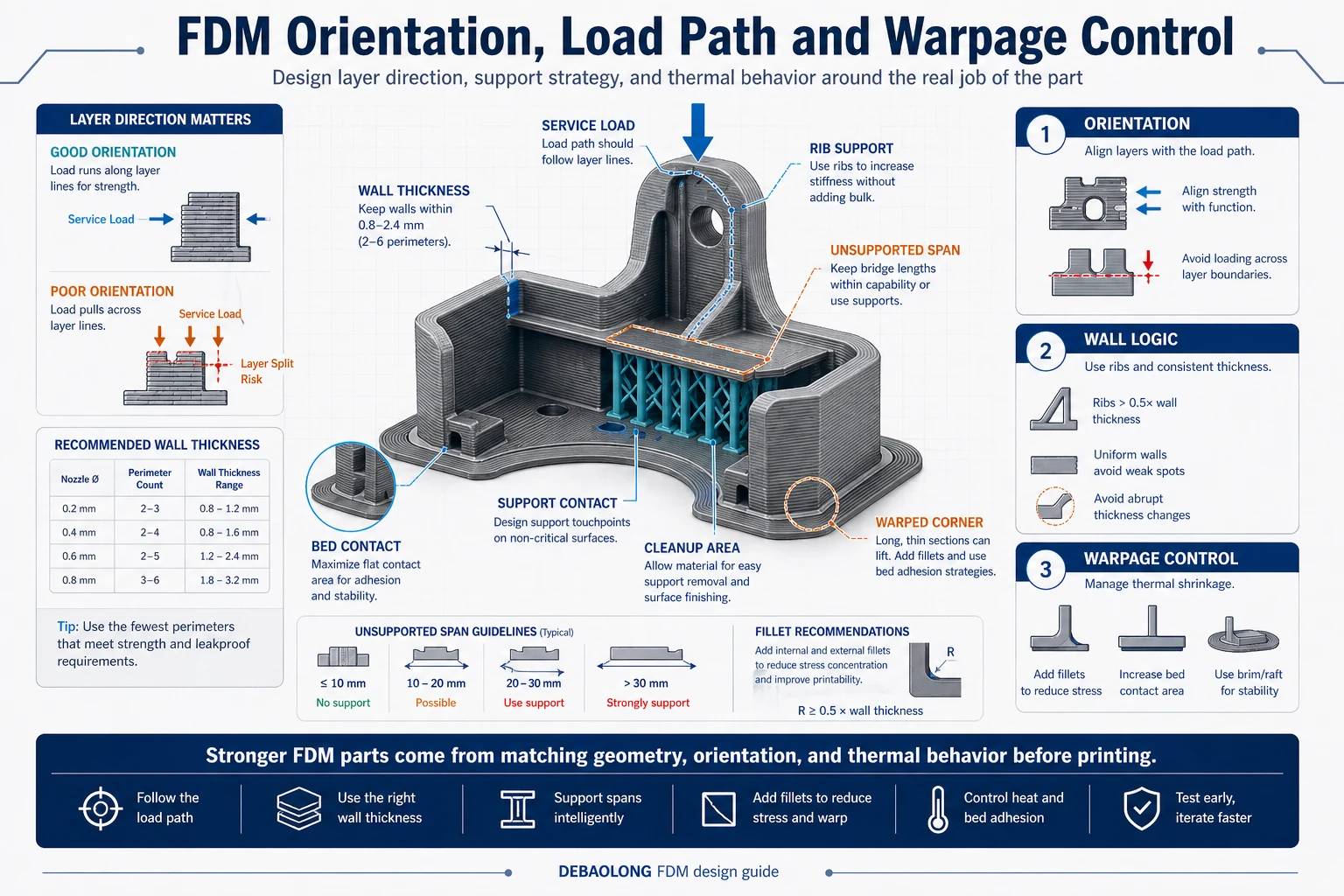
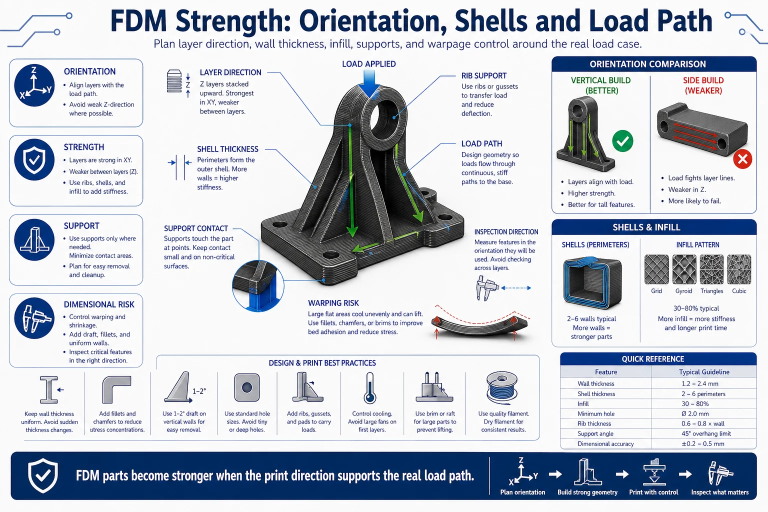
1. Match orientation and wall thickness to the load path
FDM parts are anisotropic, which means their strength changes depending on how the layers are stacked relative to the real service forces. A bracket, latch or housing clip that is strong in one orientation may fail early in another because the load is trying to separate layer boundaries rather than compress them. That is why orientation should be chosen with the functional load path in mind, not only with the goal of minimizing print time.
Wall thickness should also be chosen around the intended nozzle size and perimeter count. Random wall values can create unstable toolpaths or excess infill where solid perimeters would work better. Cleaner geometry nearly always prints more predictably.
2. Reduce unsupported spans before adding support
Overhangs and bridges are often treated as slicer problems, but they are really design problems first. Long unsupported edges, broad downward-facing surfaces and awkward bridge spans all increase the chance of droop, rough undersides and failed support removal. In many cases, a small geometry change such as a chamfer, fillet, split body or rotated feature is more effective than generating more support.
Support should be used deliberately. It helps create otherwise impossible geometry, but it also adds print time, cleanup work and possible surface damage. Good FDM design aims to reduce support on visually or functionally critical faces wherever possible.
3. Control warpage and bed adhesion through geometry
Warpage happens when different regions of the part cool at different rates and create internal stress. Large flat footprints, sharp corners and materials with greater thermal contraction all raise the risk. Designers can help by softening corners, breaking up oversized flat spans, improving base contact and using geometry that does not concentrate thermal stress into one vulnerable edge.
These changes matter because a part that lifts from the bed or twists during cooling may still look printable in the model. Real manufacturability depends on how the part behaves during the full thermal cycle, not only on how it slices.
4. Plan clearances, text and small features for real printing
Snap fits, sliding pairs, embossed lettering, pins, bosses and other fine features all need practical size choices in FDM. A hole or text detail that is technically present in CAD may be too soft or too rough in the real print if the feature is undersized or badly oriented. The same is true for pins and hooks that are left too slender relative to the layer structure.
Fine features should be reviewed not only for printability but for post-processing survival. Support removal, handling and test assembly all place stress on small geometry. If the part must function immediately after printing, the design should include that manufacturing reality from the beginning.
5. Treat FDM as a manufacturing method, not a default prototype tool
FDM is excellent for many use cases: concept parts, fixtures, housings, ergonomic models, jigs and even some functional end-use components. The process becomes much more reliable when engineers decide exactly what the part needs to prove and then shape the geometry around that purpose. A prototype shell, a functional clip and a production aid should not all be designed by the same rules.
At DEBAOLONG, we use FDM most effectively when the design team aligns orientation, wall logic, clearance and thermal behavior with the actual job of the part. That approach produces stronger prints, cleaner surfaces and fewer wasted iterations.
For related additive decisions, compare the FDM workflow article, review common FDM print problems, and compare with PolyJet design guidance.
FAQ
Why is orientation so important in FDM?
It controls layer strength, visible finish, support demand and the risk of breakage along the weakest direction.
Can geometry reduce warpage without changing material?
Yes. Better bed contact, softer corners and shorter unsupported spans often reduce warping significantly.
Is FDM suitable for functional parts?
Yes, provided the design accounts for anisotropy, clearance, support removal and actual service conditions.
Related Engineering Resources