Shenzhen, China

Explore Debaolong
Search Debaolong
Find manufacturing processes, materials, finishes, applications and engineering guidance.
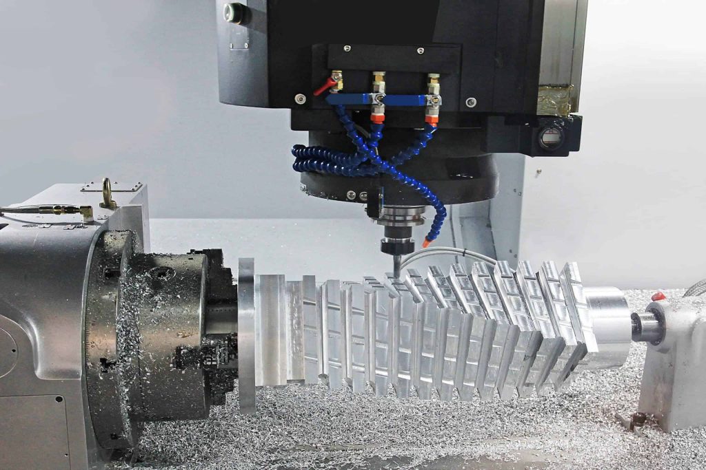
Review milling or turning through setup, material, surface intent and critical interfaces.
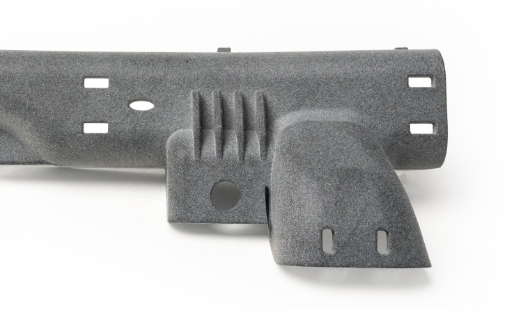
Connect process, orientation, wall, support and post-processing to the part intent.
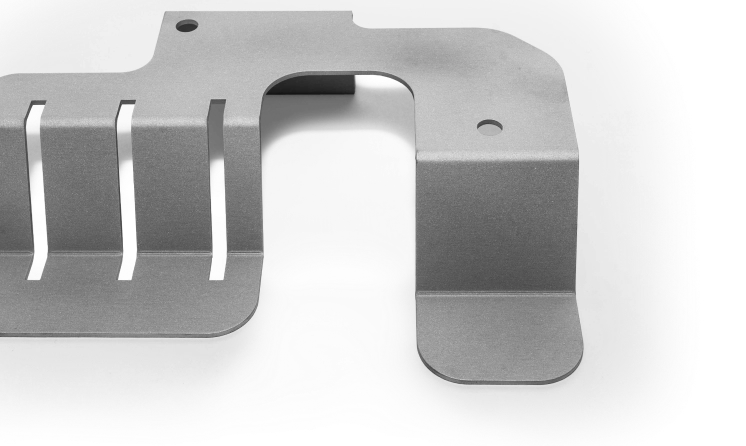
Keep gauge, bend strategy, assembly and finish decisions in one review path.
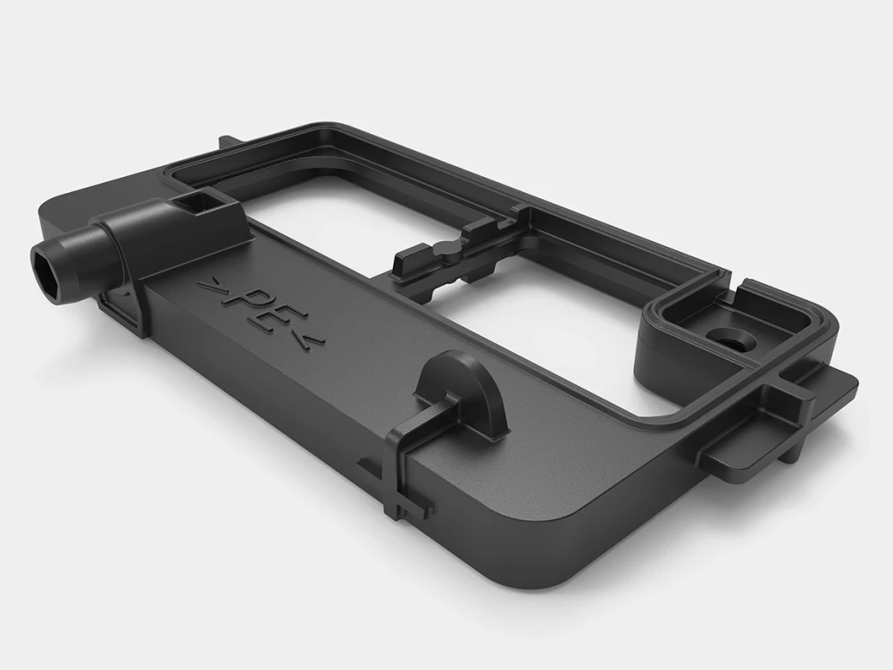
Link part geometry, polymer choice, tooling intent and repeat-production context.
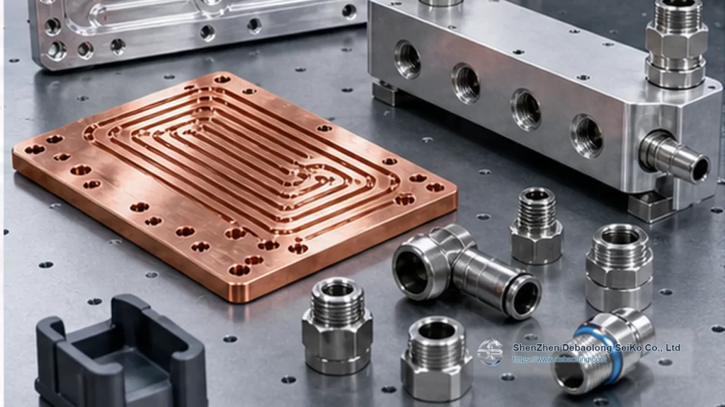
Compare strength, stability, conductivity, machinability and finish relationships.
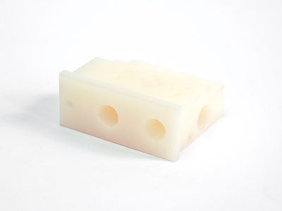
Review moisture, stability, temperature, fit and production-route implications.
Select through process, orientation, geometry and post-processing rather than a name alone.
Material choice stays connected to bend behavior, hardware, assembly and coating.
Compare surface-finishing options by material, function and manufacturing process.

Compare surface goals, material compatibility and process requirements before choosing a finish.

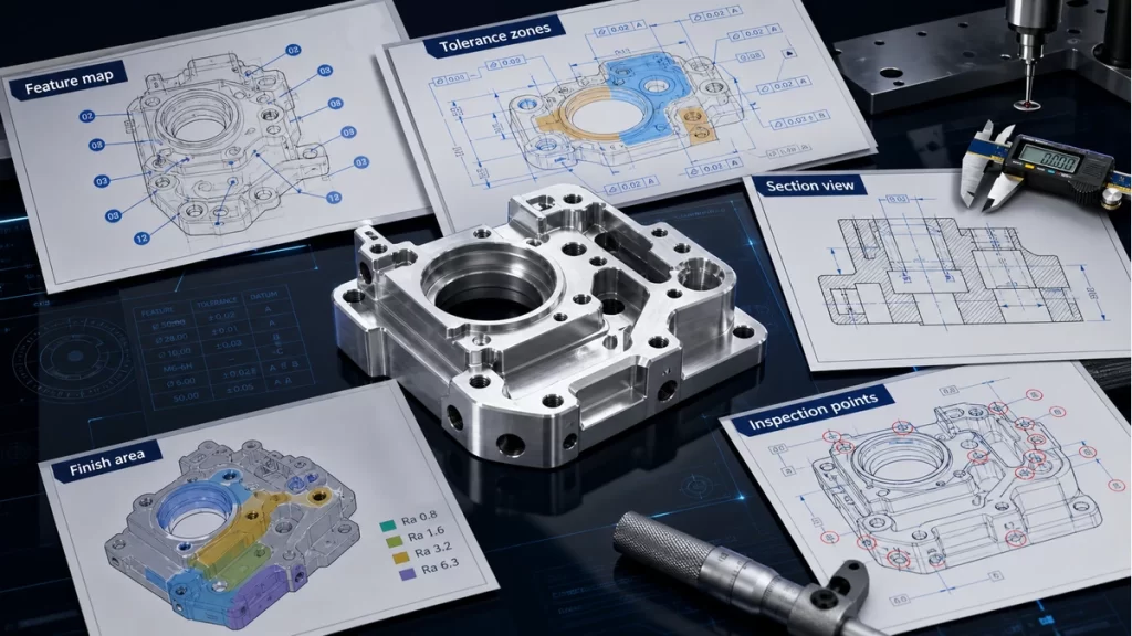
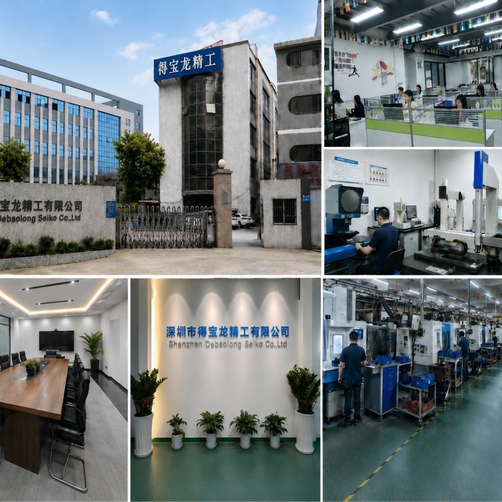
A practical manufacturing partner connecting process, materials, applications and review.
Explore factory context connected to manufacturing routes.
The factory collage shows building, workshop and manufacturing context.
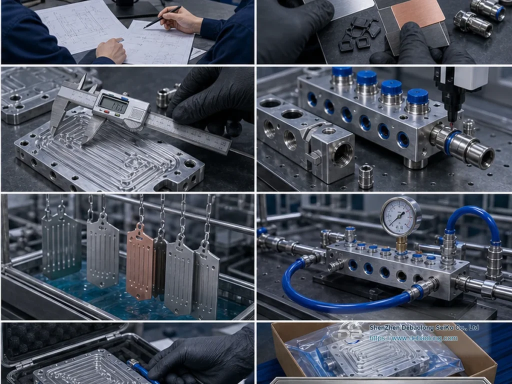
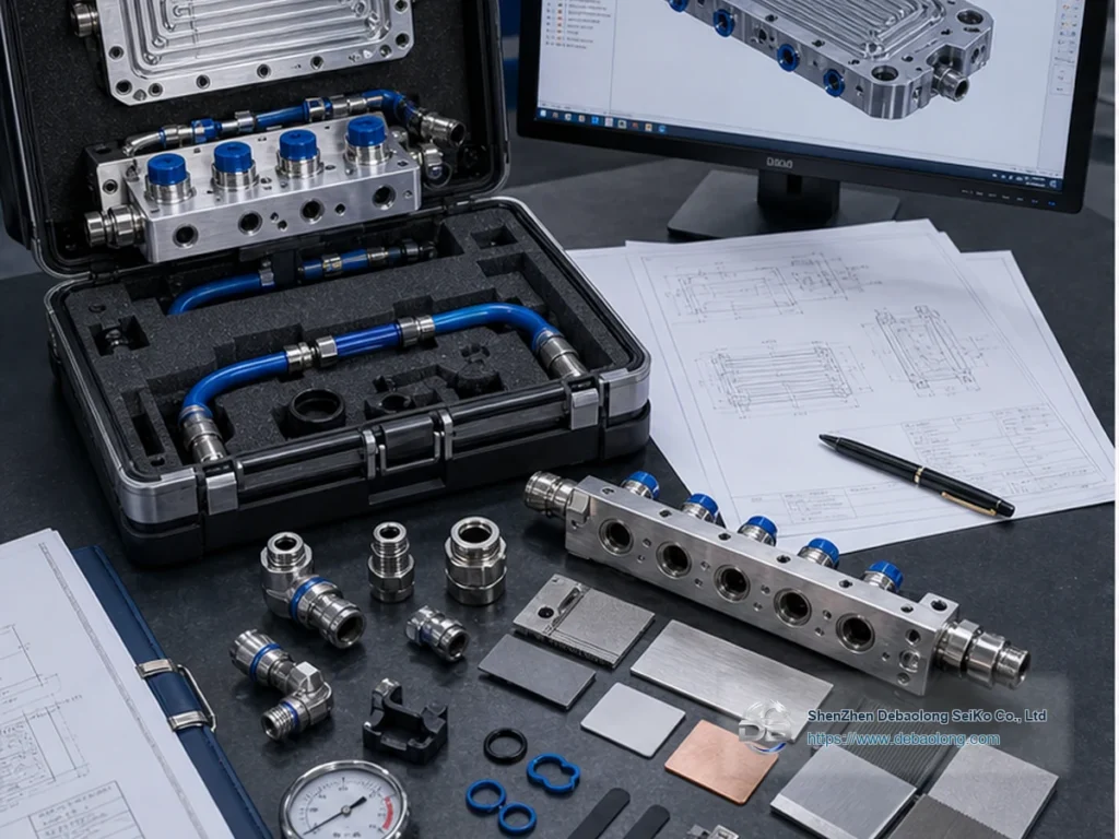
Explore inspection planning connected to manufacturing decisions and engineering review.
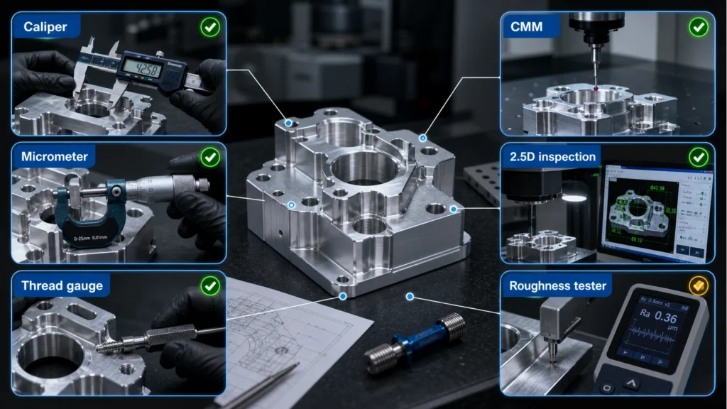
An illustrative planning graphic connects critical features, manufacturing decisions and engineering review. It is not a production inspection record.

Use Contact for general conversation or Engineering Review for a project-specific brief.