


Anodizing is a popular surface treatment process used across various industries to provide superior protection and enhance the appearance of aluminum components. Since anodizing is an electrochemical process—meaning it involves chemical immersion/exposure as well as an electric current—there must be a way to complete the electrical circuit to the part and back to the power source. This is typically done by placing the part on a rack made of a conductive material. When the rack contacts the part during the anodizing process, it can leave rack marks on its surface, where the anodized finish is usually missing. This is a concern for many, as it can affect the aesthetic quality of the finished product, especially if the part requires Type III (hard coat) anodizing and needs to be securely held throughout the anodizing cycle, particularly for parts dyed dark colors.

But the good news is that there is a simple way to reduce the impact of rack marks on anodized parts. Read on as we explore potential solutions, such as marking drawings for anodizing rack marks in non-functional or hidden features of the part. The following sections explain contact marks and the drawing questions to resolve with the anodizer.
What Are Rack Marks?
Rack marks are visible traces left on the surface of a metal part after anodizing. They are caused by small contact points between the part and the anodizing rack, which is used to hold the part and provide a path for electric current during the anodizing process.
Electrical contact must be made with each part. The contact arrangement depends on the anodizing process, current requirement, geometry and support needed during treatment. A larger part does not define one automatic rack-mark size: agree the number, location and acceptable witness areas with the anodizer. Review coating access and solution drainage together with electrical contact.

As mentioned, rack marks may be necessary depending on the part’s size (surface area). Parts must be positioned and must make contact with the rack to allow current flow during anodizing.
Where MIL-PRF-8625 is contractually required, review the applicable revision, drawing, purchase order and acceptance requirements with the anodizer. Agree allowable contact locations before processing. This article is not a compliance certificate or a substitute for the specified standard.
Why Are Rack Marks a Problem?
Rack marks can significantly affect the aesthetic quality of anodized parts, especially when they are visible on functional or visible areas of the part. Furthermore, areas with rack marks are typically unanodized or not anodized to the same thickness.
Therefore, considering the appearance and corrosion protection required for most parts, it is essential to minimize the visibility of rack marks.
Marking Drawings for Anodizing Rack Marks
One way to minimize the visibility of anodizing rack marks is to mark non-functional or hidden features of the part on the drawings that can be used for racking. Anodizing racks can then be designed to hold the part in these areas, leaving functional or visible areas free of rack marks on the exposed surface. This helps improve the part’s aesthetic quality and reduces the visibility of rack marks, especially when considering the part’s size and weight in relation to the type of anodizing process used.
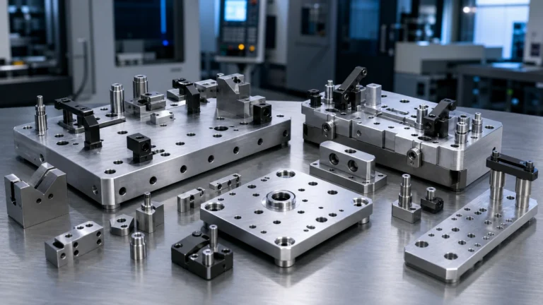
You should be aware of the most common types of anodizing racks to know where to specify allowable rack marks:
- Wiring or threading: Involves using flexible conductive wires through an agreed contact feature on the part or hanging the part in the bath and connecting it to the power source through a frame.
- Hanging: Parts are hung on a coat hanger-like design to secure them while allowing the solution to flow around them; suitable for cylindrical parts.
- Clamping: Suitable for larger or heavier parts; involves using clamps, usually securing the edges of the part.
- Spring clips: Used for spring or compression contact on the inner diameter of holes; suitable for complex geometries and quick racking.
Best Features for Racking – Rack Design Tips
The following features are best suited for specifying allowable rack marks:
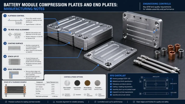
- Holes: Holes that are not critical to the part’s functionality can be used for racking.
- Countersinks and counterbores: These features can be used for racking as long as they do not affect the part’s functionality.
- Keyways and slots: These features can be used for racking as long as they are not critical to the part’s functionality.
- Tabs and shoulders: Flat surfaces that are not critical to the part’s functionality can be used for racking.
It is important to note that the design of racking features must provide good electrical contact and adequate support for the part during anodizing, as well as promote proper solution flow—since solution entrapment can degrade anodizing quality. Contact size must also be considered when designing racking features, as it depends on the anodizing process and the size of the part being anodized. Anodizing racks must not cause any distortion or deformation of the part, nor interfere with its functionality, as this could lead to finishing issues. Additionally, consulting with professionals for general references and to ensure the safety and quality of the anodizing process is important.
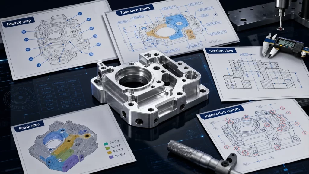
Marking permitted rack-contact areas on the drawing helps connect cosmetic requirements with the practical anodizing setup. Review support, drainage, functional surfaces, masking and inspection before processing. Acceptance must follow the agreed drawing and applicable contract; these design notes do not guarantee a particular finish quality or compliance outcome.
Discuss rack-contact and cosmetic requirements through Contact, or upload your CAD and drawing with the finish specification, quantity and marked acceptance areas.