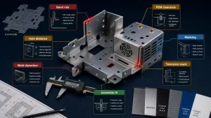
Sheet metal bending looks simple from the outside: a flat blank is held in a tool, force is applied, and the part becomes a bracket, cover, enclosure, clip, or structural panel. In production, however, a successful bend is controlled by material thickness, bend radius, feature placement, tool access, flange length, and the amount of force required to pass the material yield point without tearing or distorting the part.
This guide transforms the source bending guidance into a practical engineering checklist for DEBAOLONG readers. It keeps the original teaching flow: bend methods first, design rules next, and bend-force planning before release. For designers building brackets, covers, chassis, or laser-cut sheet metal parts, these rules help reduce trial-and-error before fabrication.
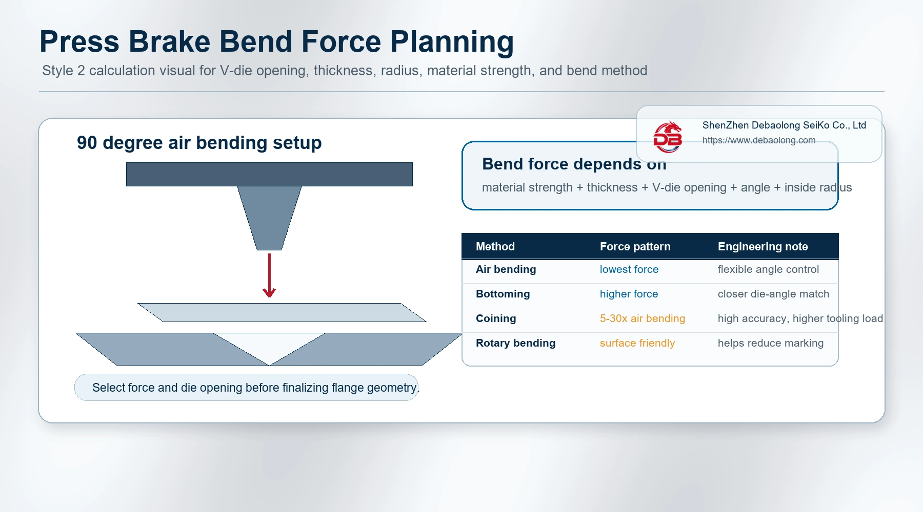
Common Sheet Metal Bending Methods
Several bending methods can be used depending on accuracy requirements, material thickness, tooling, surface finish expectations, and production volume. The chosen method affects angle control, part marking, force requirement, and cost.
Air Bending
Air bending uses an upper punch and a lower V-die. The punch pushes the sheet into the V opening, but the sheet does not fully bottom against the die faces. Because the final angle depends on punch position and springback, air bending is flexible and efficient, but it is generally less precise than methods that force the material fully into the die.
Bottoming
In bottoming, the punch presses the sheet until it contacts the die surfaces. The bend angle follows the die angle more closely than in air bending. For common mild steel work, a practical V opening is often around six times material thickness for thinner sheet and can increase for thicker plate.
Coining
Coining resembles air bending in geometry, but it uses much higher force, often many times the force of air bending. The result can be more accurate angle control and reduced springback, but tooling load, machine capacity, and surface marking must be considered carefully.
Folding
Folding holds the long edge of the sheet with a clamping beam while a folding beam rotates the free flange around the bend line. It is useful for long panels and can create positive or negative bend angles with good surface control.
Wiping
Wiping clamps the sheet and moves a tool up or down to bend the material around a profile. It can be faster than folding, but it may create more risk of scratching or local surface damage if the tool contact is not controlled.
Rotary Bending
Rotary bending uses a rotating cylindrical tool with a profile cut into it. As the roll contacts the sheet, it rotates and forms the bend. This approach can reduce sliding contact and help protect visible surfaces.
Joggle or Offset Bending
Joggle bending creates two opposite bends separated by a small web. The result is an offset feature that can help parts overlap, align, or sit flush in an assembly.
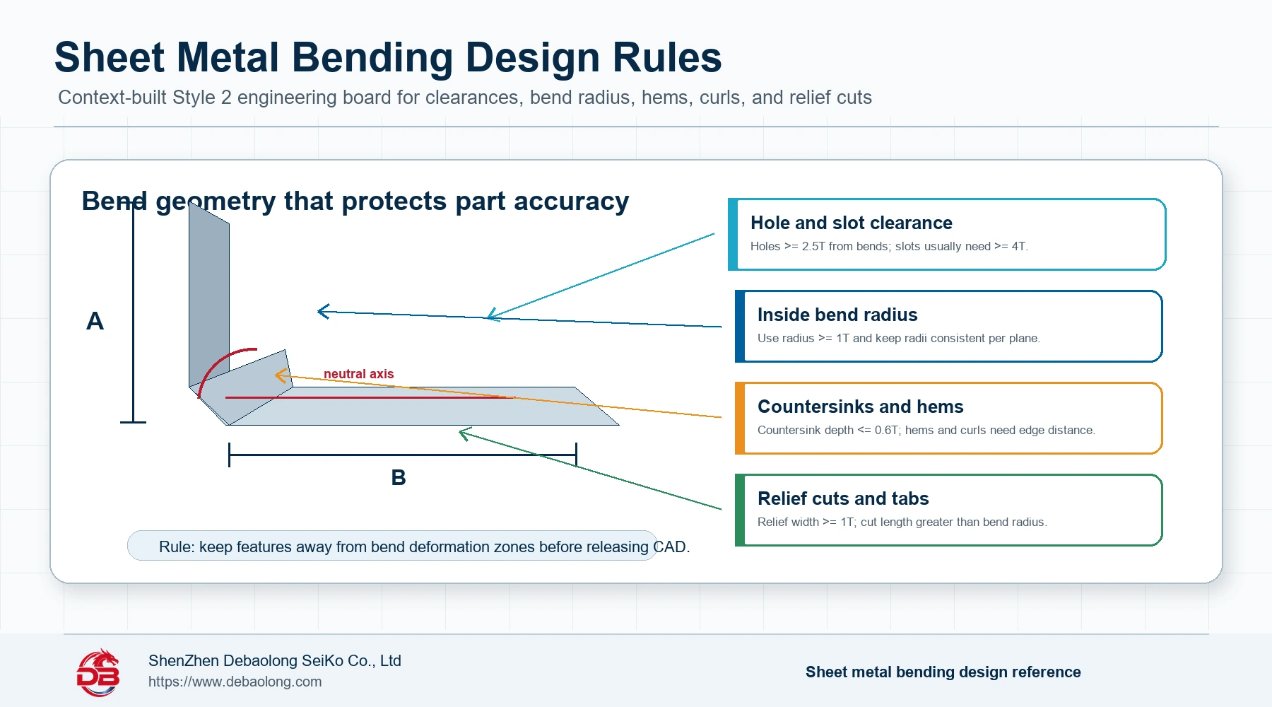
Sheet Metal Bending Design Tips
The most reliable bending designs avoid deformation around the bend zone. The following rules preserve the source article’s practical design logic while expressing the values in engineering language for production review.
1. Keep Material Thickness Uniform
Sheet metal parts should normally maintain a consistent wall thickness. Mixed thickness in one bent part can create uneven force requirements, inconsistent springback, tool interference, and costlier process planning. Thickness capability always depends on geometry, bend length, material, and machine capacity.
2. Keep Holes and Slots Away from Bend Lines
Holes placed too close to a bend can stretch, ovalize, or distort. As a starting rule, keep holes at least 2.5 times the material thickness away from the bend line. Slots need more room and should generally be at least four times material thickness away from the bend line. To reduce bulging near outside edges, keep features at least two times material thickness away from part edges where possible.
3. Use a Practical Bend Radius
The inside bend radius should normally be at least equal to material thickness. Smaller radii increase the risk of cracking, twisting, and unpredictable springback, especially on thick or hard materials. Keeping bend radii consistent across the same plane reduces tool changes and helps control cost.
Where possible, place bends in the same direction on the same plane. This reduces part reorientation during forming and improves repeatability.
4. Design Curls with Enough Radius and Clearance
A curl creates a rounded edge. Its outside radius should be at least twice material thickness. Holes near a curl should be separated from the curl by at least the curl radius plus material thickness. Other bends should be placed farther away, commonly at least six times material thickness plus the curl radius.
5. Control Countersink Depth and Spacing
Countersinks in sheet metal are often produced using secondary tooling. A conservative design keeps countersink depth within about 0.6 times material thickness. Keep countersinks at least three times material thickness from a bend, four times material thickness from an edge, and eight times material thickness from another countersink where practical.
6. Use Hem Rules According to Hem Type
Hems fold the edge of a sheet to create a safer rounded edge and improve stiffness. For an open hem, the inside diameter should be at least equal to material thickness, and the return length should be about four times material thickness. For a teardrop hem, the inside diameter should also be at least one material thickness, with an opening of at least one-quarter material thickness and sufficient run length after the radius.
7. Leave Bend Space Around Chamfered Flanges
Chamfers on flanges must leave enough material and tool clearance for the bend. A chamfer that cuts too close to the bend line can make the flange weak or cause visible distortion.
8. Avoid Continuous Bends Unless Required
Continuous bends can be difficult because already-formed sections may interfere with the die or machine frame. If continuous bends are necessary, the intermediate section should be long enough to clear tooling and allow the part to sit correctly during forming.
9. Give Notches and Tabs Enough Clearance
Notches should be placed at least three times the sum of material thickness and bend radius from a bend. Tabs should be separated from one another by at least 1 mm or one material thickness, whichever is larger.
10. Add Relief Cuts to Prevent Tearing
Relief cuts help prevent bulging, tearing, and stress concentration at the end of a bend. A practical relief cut has width at least equal to material thickness and length greater than the bend radius.
Calculating Bend Force Before Release
A correct bend requires enough force to exceed material yield strength and create plastic deformation, but not so much force that tooling, surfaces, or geometry are damaged. Bend force depends on material bending strength, sheet thickness, bend angle, inside radius, V-die opening, and the minimum internal edge available for the die.
For 90-degree bends in mild steel such as S235, engineers commonly review the relationship between sheet thickness, V-die opening, minimum internal edge, inside radius, and material strength before releasing the drawing. The source article identifies the core variables as S for thickness, V for die opening, B for minimum internal edge, and Ri for inside radius. The exact machine force should be confirmed with the fabricator’s tooling and material data.
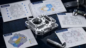
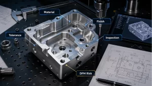
Manufacturing Review Checklist
- Confirm sheet thickness and material grade before applying clearance rules.
- Check holes, slots, notches, tabs, countersinks, hems, and curls against bend lines.
- Keep bend radius practical and consistent where possible.
- Review tool access for continuous bends and complex flanges.
- Confirm bend force and V-die opening before production release.
For broader process context, see DEBAOLONG’s sheet metal fabrication guide. If the part is still in prototype development, a structured DFM review can help prevent avoidable bending and assembly problems before tooling or production begins.
Conclusion
Good sheet metal bending design is not only about reaching the target angle. It is about controlling deformation around the bend zone, protecting nearby features, selecting practical radii, and confirming forming force before the drawing is released. When these rules are handled early, the final part is easier to fabricate, inspect, assemble, and repeat.
DEBAOLONG supports sheet metal fabrication projects involving laser cutting, bending, forming, CNC-machined inserts, and assembly-oriented DFM review. The best results come from drawings that define function clearly while leaving room for efficient manufacturing.
Related Engineering Resources