

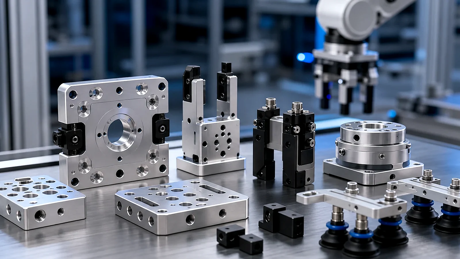
End-effector adapter plates connect the robot wrist to grippers, vacuum tooling, sensors or special handling hardware. A good adapter must be light, stiff, easy to mount and accurate enough for repeatable picking or positioning.
Application Context
How to choose between CNC machining and 3D printing for robotic end-effector adapter plates, gripper interfaces and lightweight tooling components. These parts are usually reviewed by mechanical engineers, purchasing teams and manufacturing engineers before the final supplier route is approved.
For Robotics & Automation, the right component design should connect the application requirement to a realistic manufacturing route. A good drawing package makes it clear which surfaces carry load, which holes locate the assembly, which faces are cosmetic and which features only support packaging or service access.
- robotic gripper adapters
- vacuum tooling plates
- quick-change tooling interfaces
- prototype EOAT concepts
Common Part Types
Typical custom components for this topic include the following part families. The final geometry may be machined, fabricated, printed, molded or finished by a secondary process depending on quantity and function.
- adapter plates
- gripper mounting blocks
- printed concept tooling
- machined lightweight pockets
- alignment pins
- threaded inserts
Even when a component looks simple, the details around edge quality, hole location, fastener clearance, wall thickness and coating build-up can decide whether the part assembles smoothly or creates repeated rework.
Material and Process Considerations
Material choice should be based on stiffness, weight, corrosion resistance, temperature exposure, appearance, conductivity, insulation needs and expected production volume. Prototype material can be different from production material when the first goal is fit checking or assembly validation.
- aluminum for production adapters
- printed nylon-like materials for validation
- stainless steel for wear features
- engineering plastics for soft contact components
Manufacturing Route Selection
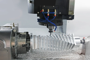
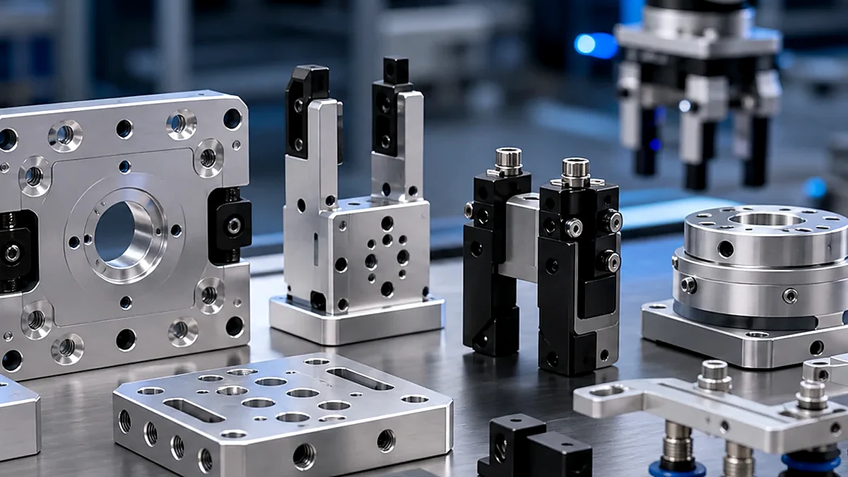
CNC machining is useful for accurate faces, threaded holes, pocket geometry and compact mechanical interfaces. Sheet metal fabrication is useful for panels, trays, covers, guards and cabinet hardware. 3D printing is useful for early validation, lightweight prototype shapes and fixture concepts. Injection molding, die casting or secondary assembly may become practical when the design and quantity support tooling.
DFM Notes Before Releasing Drawings
A focused DFM review should identify the features that truly control function. This protects the assembly while preventing the drawing from becoming more expensive than the part requires.
- robot wrist interface pattern
- mass reduction pockets
- insert pull-out risk
- tooling stiffness
- gripper alignment
- prototype-to-production differences
Useful drawings separate functional dimensions from reference geometry. They also show thread standards, insert requirements, bend notes, surface finish expectations and the difference between appearance surfaces and hidden support areas.
Surface Finishing and Assembly Notes
Surface finishing may include anodizing, passivation, nickel plating, polishing, powder coating, black oxide or other coatings where applicable. If a surface is used for contact, grounding, sealing, bearing, appearance or sliding, that requirement should be stated clearly.
Assembly-related details such as inserts, threaded holes, captive fasteners, masking, burr limits and packaging should be included in the RFQ package. Small notes at this stage often prevent late changes after the first sample run.
Inspection and Quality Planning
Inspection should match the way the part is used. Critical mounting holes, datum faces, flat surfaces, threads, bend positions, contact surfaces and cosmetic faces may need more attention than general outside dimensions. Inspection reports can be prepared according to customer requirements.
When a part is part of a larger assembly, it is helpful to explain the mating components, expected fastener pattern, load direction and any areas where measurement access is limited.
Useful External Engineering References
The following references can help engineering teams discuss manufacturing, tolerancing or application requirements with a common vocabulary:
- ASTM Committee F42 on additive manufacturing technologies
- NIST robotics and manufacturing automation
RFQ Checklist
To prepare a fast and accurate quotation for robotic end-effector adapter plates, please send:
- 2D drawings and 3D CAD files
- Material, quantity and expected annual demand
- Critical tolerance, datum and inspection requirements
- Surface finish, coating, masking or appearance requirements
- Assembly, insert, fastening or packaging requirements
- Prototype stage, validation purpose or production usage notes
How Debaolong Supports This Type of Part
Debaolong supports custom component manufacturing from prototype to production through drawing review, process selection, CNC machining, sheet metal fabrication, 3D printing, plastic part support, surface finishing and inspection. The team can help evaluate whether a part should start as a prototype, a small-batch machined component, a fabricated assembly or a production-ready part.
For a broader view of this application area, visit the Robotics & Automation solution page or the Manufacturing Engineering Knowledge Center.
FAQ
What information should be included in the RFQ?
Send 2D drawings, 3D files, material requirements, quantity, surface finish notes and any critical assembly or inspection requirements.
Can prototype parts use a different manufacturing route than production parts?
Yes. A prototype may use 3D printing, CNC machining or simplified sheet metal to validate fit before the final production route is selected.
How should critical tolerances be shown on the drawing?
Mark functional datums, mounting faces, hole patterns, flatness and inspection-critical features clearly, while leaving non-critical geometry under a practical general tolerance.
Can Debaolong support both mechanical parts and finishing?
Debaolong can support CNC machining, sheet metal fabrication, 3D printing, injection molding, surface finishing and inspection based on drawings and project requirements.
How can unnecessary manufacturing cost be reduced?
Avoid over-tolerancing, define only functional cosmetic surfaces, keep tool access practical and share the expected quantity early so the process route can be selected correctly.
Need custom robotic end-effector adapter plates? Send drawings, STEP files, material requirements, quantity, tolerance notes and surface finish needs through the Robotics & Automation solution page.