Automation fixtures are only useful when they locate parts in the same position cycle after cycle. A fixture may look strong and complex, but if its datum surfaces, locating pins, stops and clamp access are not defined clearly, production variation can appear during loading, machining, inspection or robotic handling. Good fixture design starts with a simple question: which surfaces control the part, and how will the operator or robot repeat that position every time?
Why Datums Matter in Automation Fixtures
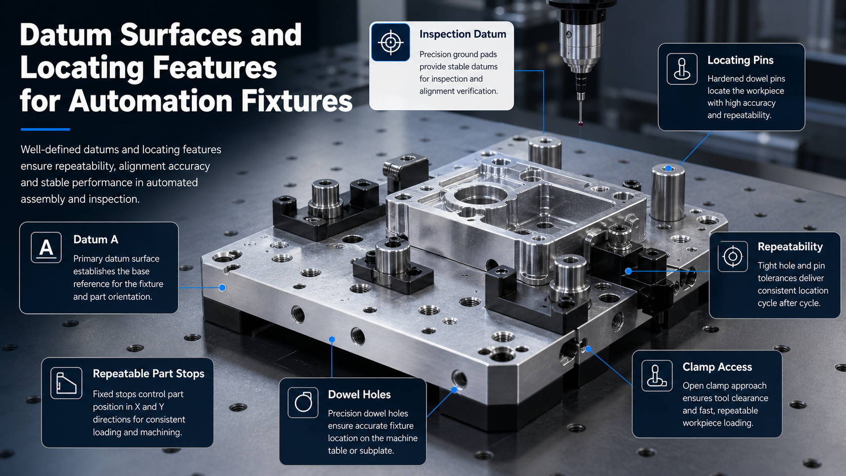
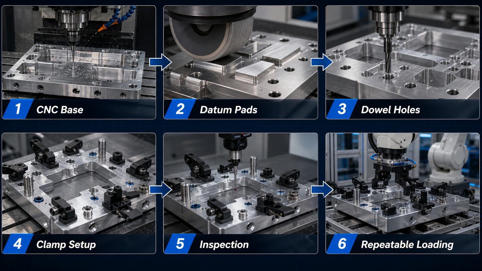
Datum surfaces establish the reference system for a fixture. They define how a part sits, how it is measured and how repeatability is maintained between loading cycles. In automation equipment, inspection jigs, robotic stations and assembly fixtures, datums are often more important than the number of clamps. If a part rests on unstable surfaces or locates from cosmetic edges, the fixture may repeat poorly even if the clamp force is high.
For robotics and automation projects, datum quality connects directly to custom manufacturing. A fixture base may need CNC machined datum pads, reamed dowel holes, hardened locating pins, threaded clamp points and inspection reference features. Debaolong supports these parts as part of robotics and automation components, especially when precision machined fixture hardware must work with sheet metal guards, printed validation parts or sensor brackets.
Primary, Secondary and Tertiary Location
A practical fixture usually constrains a part through primary, secondary and tertiary references. The primary datum supports the largest or most stable surface. The secondary datum controls orientation. The tertiary datum prevents the remaining degree of freedom from drifting. This logic helps avoid overconstraint and makes it easier to inspect the final fixture. The exact scheme depends on part geometry, tolerance needs, loading direction and whether the fixture is used for machining, welding, assembly or inspection.
Locating pins, stops and datum pads should contact reliable features on the workpiece. Avoid using burr-prone edges, flexible tabs or unfinished surfaces as critical references. If a fixture must hold a sheet metal part, the designer should consider bend variation and coating thickness. If it holds a CNC machined part, machined reference faces and dowel holes may be appropriate. These decisions should be shown clearly in the drawing and 3D model.
Locating Pins, Dowel Holes and Part Stops
Locating pins are common because they provide repeatable position with compact geometry. However, pin design requires attention to fit, access and wear. A round pin can control two directions. A diamond pin or relieved pin may help avoid overconstraint when two holes locate one part. Dowel holes in the fixture base should be machined and inspected carefully because their position controls the whole locating system.
Part stops are useful when a workpiece is loaded against a shoulder, rail or block. They should be strong enough for repeated contact but not so large that they block cleaning, chip removal or tool access. When fixtures are used around automation, stops should also allow predictable loading from a robot gripper or slide mechanism. Similar concerns appear in automation fixtures and jigs and sensor and camera mounts for machine vision systems.
Clamp Access and Loading Direction
Clamps should secure the part without fighting the locating system. If clamp force pushes a part away from its datum, repeatability suffers. Clamp arms, screws and toggle mechanisms also need enough access for tools, robotic loading, operator hands and maintenance. A fixture that is easy to machine but difficult to load will slow the production cell.
Designers should review the loading path in 3D. Check whether a robot gripper can approach the fixture, whether the part can clear locating pins, whether clamps swing without collision and whether chips or debris can be removed from datum areas. For inspection fixtures, make sure the measurement probe, dial indicator or CMM stylus can reach the required features.
CNC Manufacturing Notes for Fixture Bases
Fixture bases are often made from aluminum or steel depending on stiffness, wear, weight and cost. Aluminum is easier to machine and handle, while steel can provide better wear resistance and rigidity in demanding applications. Critical surfaces may need face milling, grinding or careful finishing. Holes for dowel pins, bushings and locating hardware should be specified with appropriate tolerance and inspection requirements.
- Datum pads: define whether pads are milled, ground or otherwise finished.
- Dowel holes: specify diameter tolerance, positional tolerance and whether reaming is required.
- Threaded holes: show thread depth, insert requirements and expected clamp hardware.
- Relief pockets: add clearance for chips, weld beads, formed edges or part variation.
- Inspection references: mark surfaces and holes that should be used for fixture verification.
Debaolong can support CNC machining for fixture bases, locating blocks, adapter plates and precision brackets. For early development, 3D printing can also help validate loading direction, operator access and part clearance before the metal fixture is finalized.
Tolerance, Inspection and Repeatability Checks
Fixture drawings should separate ordinary dimensions from repeatability-critical features. Not every pocket or clearance cutout needs tight tolerance. Datum pads, dowel holes, locating pin positions and clamp reference points deserve more attention. Over-tightening every dimension increases cost without improving the fixture function.
Inspection may include CMM checks, 2.5D measurement, pin gauge checks, thread checks, surface finish review and assembly fit checks. For production fixtures, it is useful to define a verification method: how the fixture will be checked when new, how it will be maintained and what wear surfaces may need replacement. Engineering references such as ISO 5459 for datums and datum systems can support datum discussions, while final drawing requirements should match the project specification.
RFQ Checklist for Automation Fixture Parts
- 2D drawings and 3D CAD files for the fixture base and locating components.
- Workpiece model or sample part information where available.
- Required datum surfaces, locating pins, part stops and clamp positions.
- Material requirements for base plates, pins, blocks and wear components.
- Tolerance requirements for dowel holes, datum pads and locating features.
- Expected loading method: operator, robot, slide, pallet or inspection station.
- Surface finish, coating or hardening requirements if relevant.
- Quantity, prototype needs and inspection report requirements.
FAQ
Should a fixture use two round locating pins?
Two round pins can overconstrain a part if the hole spacing varies. In many designs, one round pin and one relieved or diamond pin can provide better repeatability without forcing the workpiece.
Which fixture features should receive the tightest tolerances?
Datum pads, dowel holes, locating pin positions and critical stop surfaces usually deserve the most attention. Clearance pockets and non-contact shapes can often use looser tolerances.
Can 3D printing help before machining a fixture?
Yes. 3D printed validation models can help check loading direction, clamp access, operator clearance and workpiece fit before investing in a CNC machined fixture base.
What information helps quote automation fixture components?
Send the fixture model, workpiece model, datum scheme, material requirements, tolerance notes, expected loading method and quantity. Inspection requirements should also be included if repeatability is critical.
Need custom automation fixture parts or locating hardware? Send drawings, STEP files, datum requirements, tolerance notes and fixture function through the Debaolong contact page. The team can help review a practical manufacturing route from prototype validation to production use.