
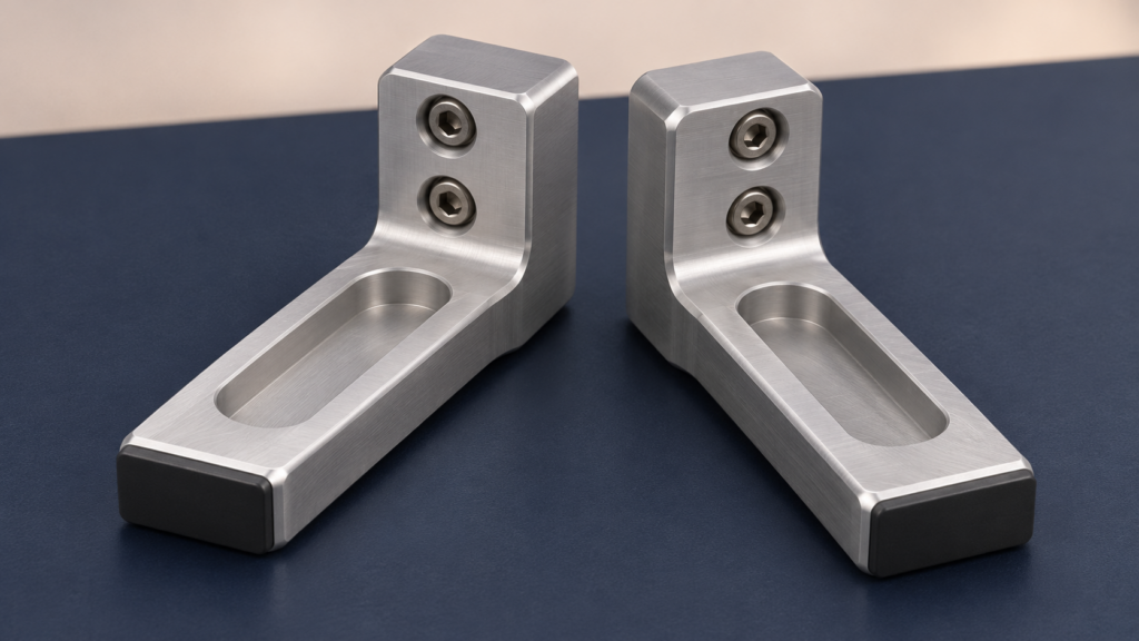
The useful result of a weight-reduction project is not a lighter CAD model. It is a lighter tool that still holds, locates and releases the workpiece as intended.
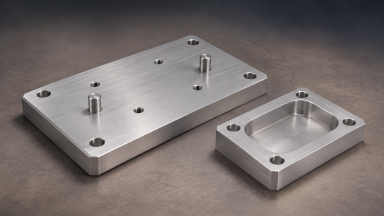
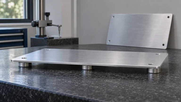
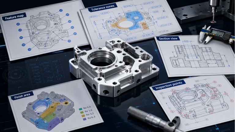
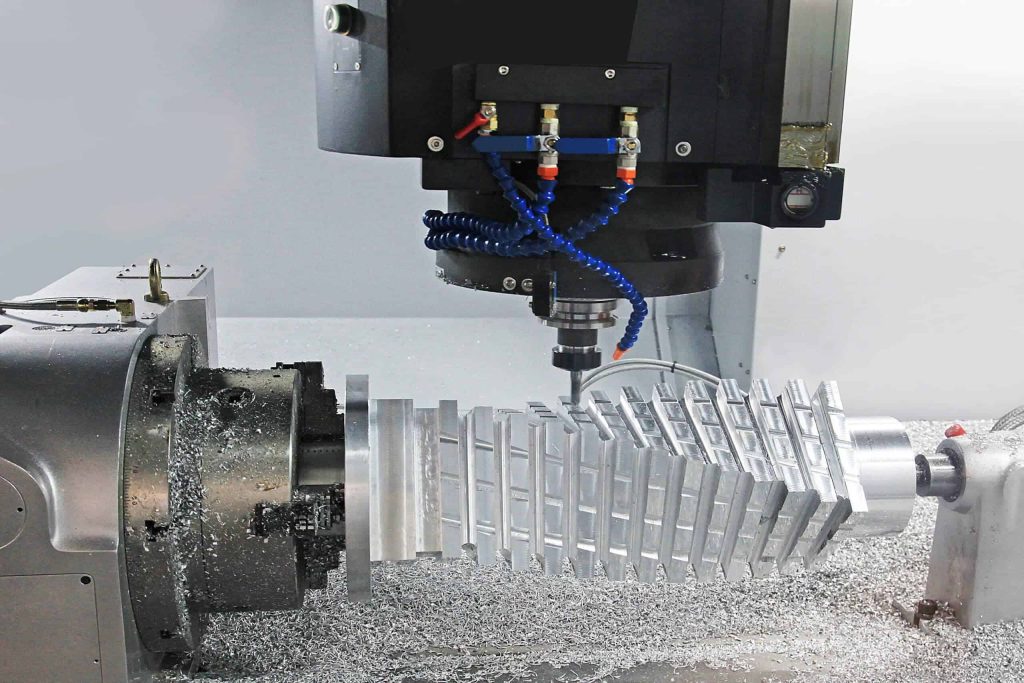
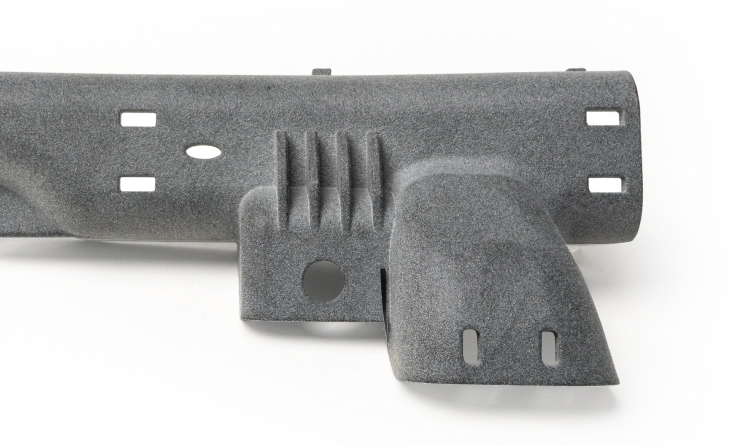
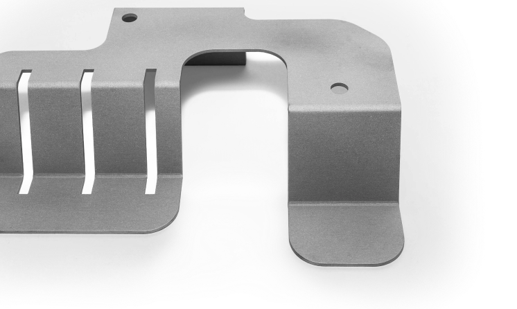
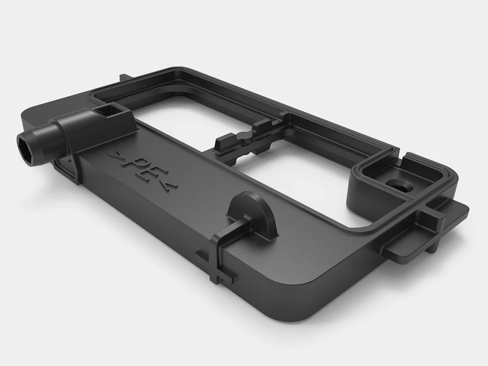
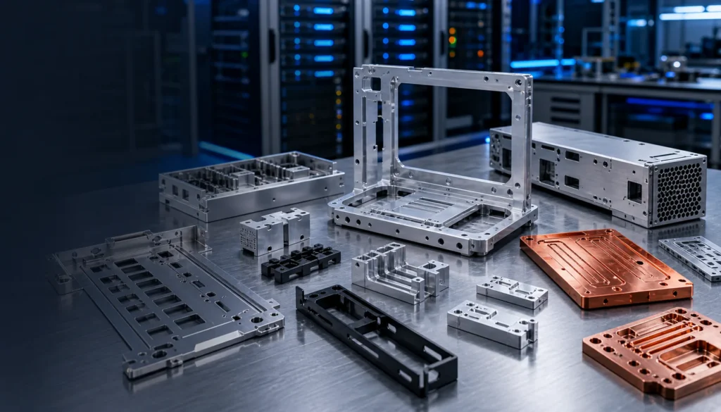
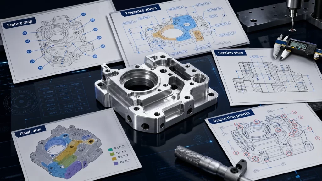
Images in this article are illustrative tooling concepts, not production drawings or tested load-rated assemblies.
Industrial robotics continues to expand. In September 2026, the International Federation of Robotics reported that approximately five million industrial robots were operating worldwide in 2025. More automation brings more application-specific tooling, including the small fingers and adapters that connect a robot to its workpiece. IFR report
For an existing gripper finger, a pocket or thinner section can look like an obvious improvement. The decision becomes less straightforward when the revised finger must reach farther, avoid a fixture or carry a different contact pad.
Before removing material, define what must remain unchanged: the holding condition, contact position, clearances and repeatability of the assembled tool.
1. Establish the baseline before changing the drawing
Start with the configuration that is actually being evaluated, not an isolated finger model.
Record the gripper model, finger revision, mounting hardware, contact pads and intended workpiece. Establish the complete tool mass and where the workpiece sits when held. Include motion requirements, not just a stationary pose.
Universal Robots’ payload guidance, for example, considers the gripper and workpiece together and addresses centre-of-gravity offset and inertia. These factors can affect acceleration and must be checked against the selected robot’s documentation. They cannot be inferred from the finger’s mass alone. Universal Robots: Maximum Payload
Keep a copy of the baseline CAD model, controlled drawing and assembly configuration. Without that reference, it is difficult to distinguish an improvement from an unrelated change introduced during prototyping.
2. Treat extra reach as a new load condition
A finger that extends farther to clear a feature may weigh almost the same as the original. That does not make the change mechanically neutral.
For a force acting perpendicular to a lever arm, the simplified bending-moment relationship is:
M = F × L
At the same force, increasing that lever arm by 20% increases the moment by 20%. This is a basic illustration of leverage, not a complete gripper-sizing or safety calculation.
The mounting arrangement, load direction and motion still need evaluation. Check the manufacturer’s permitted finger geometry, mass and loads for the exact gripper model. Do not borrow a limit from a similar-looking unit.
If the new design changes the point of contact, record that change explicitly. It may affect both the force path through the finger and the position of the held workpiece.
3. Review stiffness, not just survival
A finger can remain intact yet move enough under load to disrupt the next operation.
That distinction matters when a robot places a part into a nest, presents it for inspection or inserts it into another component. A successful pick does not show that the contact point remains within the required positional limits.
Trace the load path from the contact surface to the mounting interface. Examine abrupt section changes, pocket ends, narrow material around holes and the transition into the mounting end.
On the drawing, distinguish:
- Protected regions: locating features, fastening support and load-critical areas identified by the designer.
- Permitted relief regions: areas where removal has been reviewed.
- Functional inspection features: surfaces and dimensions that control the workpiece position.
Do not leave the machinist to decide which material is structurally dispensable.
4. Connect each change to a validation check
A short change-review table is often more useful than a long list of generic tolerances.
The following is a planning aid, not a universal acceptance specification. The designer and integrator must define the actual limits.
| Proposed change | What to compare with the baseline | Evidence needed before release |
|---|---|---|
| Extend the finger or move the contact point | Reach, load direction and moment arm | Updated application-load review and clearance checks |
| Add or enlarge a relief pocket | Remaining load path and contact-point movement | Design review and a defined stiffness/functional check |
| Change material or manufacturing process | Relevant material behaviour and service conditions | Material/process record and appropriate functional validation |
| Add or change a contact pad | Contact position, compression and retention | Holding and positioning checks under representative conditions |
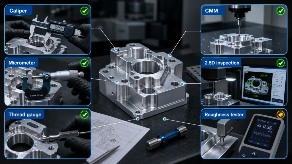
| Change locating or fastening features | Seating, assembly method and replacement position | Dimensional inspection and reassembly check |
| Add or change a finish | Functional dimensions and contact behaviour | Inspection at the specified acceptance stage |
| Change the workpiece or robot motion | Payload configuration and operating loads | Updated application review and representative motion trial |
Avoid recording only “PASS.” Record the configuration, test conditions, measured result where applicable and the acceptance criterion used.
5. Keep contact pads in the assembly review
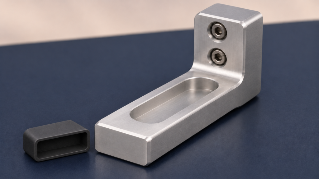
A replaceable pad can protect a surface or make wear maintenance easier. It also introduces another locating and fastening interface.
Specify which workpiece surfaces may be contacted, whether visible marking is acceptable and how much pad movement or compression the application allows. Define how the pad is retained and how its position will be checked after replacement.
A softer pad should not be used to hide an uncertain fit. Increasing gripping force is not a substitute for understanding the contact condition.
For an overview of manufacturing routes and common tooling components, see our existing end-of-arm tooling guide. This review focuses on what changes when an established finger design is revised.
6. Give each prototype a specific job
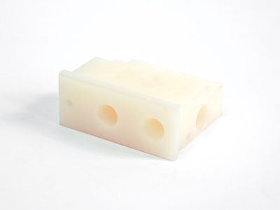
A printed model may answer whether the finger reaches the part and clears the fixture. It does not automatically establish the service life of a production tool.
State whether the prototype is intended for:
- A geometry and access check.
- A functional trial with defined limits.
- Evaluation as a final production component.
Record the selected process, material, orientation and post-processing. These details matter if the result will support a design decision.
Formlabs’ manufacturing-aid guidance discusses functional-surface orientation and the risk of creep in continuously loaded SLA parts. The practical lesson is to assess the selected material and conditions rather than treating all printed fingers as interchangeable. Formlabs: Manufacturing aids
7. Release the revised assembly, not just the revised part
Before the trial, agree what successful operation means.
Depending on the application, the plan may include workpiece variation, representative contact conditions, expected motion, repeated cycles and checks after removing and reinstalling a finger or pad.
Use the complete intended assembly. Record its revision and configuration. If the finger geometry, pad, workpiece or motion changes afterwards, identify which results remain valid and which checks must be repeated.
This is a component-design and manufacturing review. It does not establish the safety of a complete robotic cell, which requires assessment and validation by the responsible integrator.
Preparing a focused manufacturing RFQ
For a revised gripper finger, send the baseline and proposed revision together where possible. Include:
- The gripper model and mounting-interface information.
- STEP models and controlled 2D drawings.
- Marked changes and protected features.
- Workpiece geometry and intended contact areas.
- Material, finish and pad requirements.
- Critical dimensions and inspection expectations.
- Prototype, repeat-order and spare-part quantities.
- Available load and motion information.
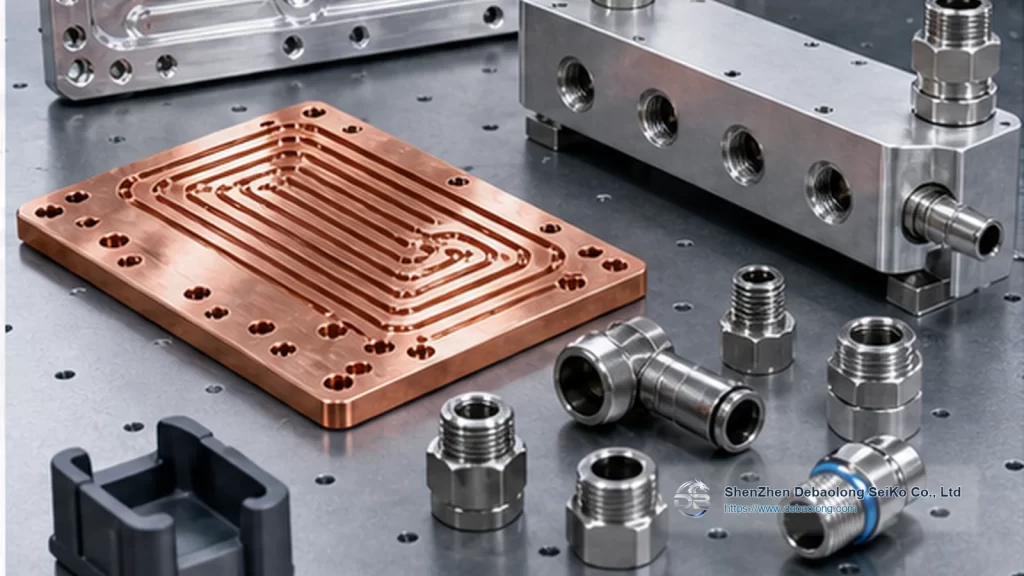
Debaolong’s Robotics & Automation resources connect these applications with CNC machining and additive manufacturing.
Remove material only when the reason is clear, the affected functions are identified and the revised assembly has a defined route to acceptance.