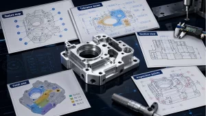
CNC machining diagrams help procurement engineers send clearer RFQs because they make function, tolerance priority, surface finish, assembly risk and inspection expectations visible. Text notes alone often leave room for interpretation. A supplier can quote more accurately when the buyer marks datum faces, locating holes, threaded features, sealing surfaces, coating-sensitive areas, DFM risks and inspection methods. The best diagrams are not decorative. They reduce ambiguity, help the buyer compare supplier responses fairly, and make sure cost, lead time and quality evidence are based on the same manufacturing requirement.

Why Diagrams Improve CNC Sourcing Communication
A CNC drawing may contain all the necessary information, but different stakeholders read it through different priorities. A design engineer may focus on function, a buyer may focus on cost and delivery, and a machinist may focus on tool access, workholding and inspection. Diagrams create a shared visual layer that points to the exact feature being discussed. Instead of saying “this area is important,” the buyer can mark the datum, hole, thread, groove, sealing face or cosmetic surface that controls the part.
This matters in international sourcing because every clarification cycle costs time. A short diagram can prevent several email rounds by showing what the part does and where the supplier should focus. It also makes quote comparison more honest. If all suppliers receive the same feature map, tolerance priority and inspection diagram, the buyer is less likely to compare a loose assumption from one supplier against a strict interpretation from another.
For precision CNC machining, diagrams are especially useful when a part includes tight fits, sealing interfaces, cosmetic areas, coating, multiple setups or demanding inspection evidence. They help the supplier ask better questions before material is ordered and before fixtures are planned.
Functional Feature Map
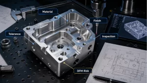
A functional feature map identifies the features that control the part’s purpose. For a machined bracket, the important areas may be datum faces, locating holes and threaded holes. For a fluid or thermal component, the key features may include sealing surfaces, O-ring grooves, port faces and flatness-controlled interfaces. For a visible housing, cosmetic surfaces and protected edges may matter more than the outside profile. For a fixture plate, dowel holes, pin locations, datum surfaces and repeatability-critical areas deserve attention.
The map should also show non-critical areas. This is often the most valuable part of the diagram because it tells the supplier where normal machining variation is acceptable. If every feature appears equally important, suppliers may quote excessive control. When the buyer marks a non-critical outside profile or cosmetic-only zone, the supplier can keep the process practical while protecting the features that affect function.

Tolerance Priority Diagram
A tolerance priority diagram separates dimensions into A, B and C groups. A-level dimensions are critical functional features: bearing fits, sealing faces, datum relationships, locating hole positions, flatness, perpendicularity, concentricity or any dimension that directly affects assembly. B-level dimensions are important but usually lower risk: clearance holes, cover alignment, mounting relationships or service-access geometry. C-level dimensions are general non-critical features where a practical baseline tolerance is normally acceptable.
This diagram helps procurement avoid two opposite mistakes. The first mistake is under-specifying a functional feature so the supplier does not control it tightly enough. The second is over-tolerancing the entire part, which increases cost and inspection effort without improving function. The diagram does not replace numerical tolerances; it explains priority. The drawing still needs tolerance values, datum references and GD&T where appropriate.
Debaolong’s CNC machining cost reduction guide explains why tolerance priority is one of the strongest levers for controlling cost and lead time.

Assembly Cross-Section Diagram
Many CNC part risks are hidden inside the assembly. A top view may show hole positions, but it may not show shaft engagement, O-ring compression, screw clearance, countersink depth, coating thickness, gasket interface or possible interference. A cross-section diagram cuts through the assembly and shows the relationship between the machined part and mating components.
Cross-sections are useful for holes, bores, shoulders, counterbores, threaded inserts, press fits, grooves and sealing interfaces. They help the supplier understand why the feature exists, not only what shape it has. An O-ring groove should be treated as a sealing feature, not simply a rectangular slot. A shaft-hole fit may need a controlled bore size and finish. A screw clearance may need protection from coating build-up. If these relationships are visible before quoting, the supplier can discuss the manufacturing route more accurately.

Surface Finish and Coating Impact Diagram
A surface finish diagram shows which areas receive finishing, which areas are cosmetic, which areas need masking and which dimensions should be inspected after finishing. This is important because finishing is often performed after machining and may be handled by a specialist process supplier. If finishing requirements are vague, a part may be machined correctly but finished incorrectly.
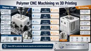
Anodizing and hard anodizing can affect holes, slots, threads and sliding fits. Nickel plating can create build-up on precision surfaces. Powder coating can be thick enough to create assembly interference unless protected areas are defined. Stainless steel passivation is different from polishing. A useful diagram marks cosmetic surfaces, sealing surfaces, threaded areas, protected bores, grounding or contact surfaces and laser-marking locations. If the buyer is comparing metal and plastic options, Debaolong’s guide to manufacturing materials can help prepare material and finish decisions before the RFQ.
DFM Risk Heatmap
A DFM risk heatmap marks features that may make the part expensive, unstable or difficult to inspect. Common CNC risks include deep pockets, thin walls, sharp internal corners, deep holes, long slender features, small cutters, awkward clamping areas, multi-side machining and deformation-sensitive zones. These features do not automatically make a design impossible. They mean the supplier should review the manufacturing route before quoting.
The heatmap is useful for procurement because it turns a complex drawing into a focused question list. Can a deep pocket radius be increased? Can a thin wall be thickened? Can a sharp corner accept a cutter radius? Can a deep blind hole become a through-hole? Can cosmetic areas be moved away from clamp zones? Even small changes can reduce machining time, tool risk, burr risk and inspection difficulty.

Inspection Method Diagram
An inspection method diagram matches features to measurement tools. General outside dimensions may be checked with calipers. Thickness, diameters and precision widths may need micrometers. Threaded holes should be checked with suitable thread gauges. Datum relationships, GD&T features and critical hole patterns may require CMM inspection. Flat 2D hole patterns, slots and profiles may be suitable for 2.5D inspection. Functional surfaces may need roughness testing, and some production fixtures may require go/no-go gauges or custom inspection fixtures.
Procurement engineers should define inspection evidence before the order is placed. A first article inspection report is useful when the part is new, the tolerance is tight or the manufacturing route has not been proven. For repeat production, the inspection plan may shift toward critical dimensions and sample checks. The diagram should assign the right tool to the right risk, not demand every tool for every feature.
Complete RFQ Package Diagram
The complete RFQ package diagram shows all information a CNC supplier needs before quoting: STEP file, 2D PDF drawing, material grade, quantity, tolerance requirements, surface finish, inspection needs, application details, annual volume or repeat demand, target lead time and packaging requirements. For complex parts, the package may also include assembly images, mating-part drawings, finish samples, critical-feature screenshots or an inspection checklist.
This diagram is helpful because missing information often hides inside the RFQ process. A buyer may send a STEP file but forget the drawing. The drawing may show a finish note but not the final color. The buyer may request a quote for 10 parts without mentioning annual demand. Each missing detail changes cost, lead time and manufacturing planning.

Which CNC Diagrams Should Procurement Send?
The most useful diagram depends on the risk of the part. A simple bracket may only need a feature map and tolerance priority note. A sealing component may need a cross-section and surface finish diagram. A complex housing may need a DFM heatmap, inspection method diagram and complete RFQ package checklist. The table below helps buyers choose the right diagram type instead of adding visual material that does not improve the quote.
CNC Diagram Types That Improve RFQ Accuracy
| Diagram Type | What It Shows | Why Procurement Engineers Need It |
|---|---|---|
| Functional feature map | Datum faces, locating holes, threads, sealing surfaces, cosmetic areas and non-critical zones. | Helps the supplier focus machining and inspection on features that control function. |
| Tolerance priority diagram | A/B/C separation of critical, important and general dimensions. | Prevents unnecessary tight tolerance while protecting fit, sealing and assembly. |
| Assembly cross-section | Shaft fits, O-ring grooves, screw clearance, coating thickness and interference risk. | Reveals hidden assembly relationships that are not obvious in a top view. |
| Surface finish impact diagram | Cosmetic surfaces, masking zones, coating build-up and post-finish dimensions. | Reduces the risk that a correctly machined part becomes wrong after finishing. |
| DFM risk heatmap | Deep pockets, thin walls, internal corners, deep holes, clamping and deformation zones. | Creates a focused DFM discussion before the quote and schedule are fixed. |
| Inspection method diagram | Which tools inspect which features: caliper, micrometer, thread gauge, CMM, 2.5D or roughness tester. | Aligns supplier quality evidence with buyer expectations before production. |
| Complete RFQ package diagram | STEP, PDF, material, quantity, finish, tolerance, inspection, application, lead time and packaging. | Shows whether the supplier has enough information to quote the real manufacturing requirement. |
How Debaolong Uses Engineering Diagrams to Improve CNC Communication
Shenzhen Debaolong Seiko Co., Ltd. can review STEP files, 2D drawings, material requirements, surface finishing notes, tolerance priorities and inspection expectations for custom CNC machined parts. Debaolong uses diagrams as a communication layer, not as a replacement for drawings. When a diagram shows functional features, coating-sensitive areas or DFM risks, the supplier can ask better questions and the buyer can approve better trade-offs.
Buyers who want broader process education can also use Debaolong’s manufacturing engineering knowledge center to compare CNC machining, 3D printing, sheet metal fabrication, injection molding, material options and DFM topics before preparing an RFQ.
Debaolong Engineering Note: The best RFQ diagram is not the prettiest diagram. It is the one that makes a machining risk visible early enough for the buyer and supplier to solve it before material is ordered, fixtures are planned or finishing requirements are locked.
FAQ
Why are diagrams useful when requesting CNC machining quotes?
Diagrams reduce ambiguity. They show functional features, tolerance priority, surface finish zones, assembly relationships and inspection needs so the supplier can quote the real manufacturing requirement.
What is a CNC DFM diagram?
A CNC DFM diagram highlights manufacturability risks such as deep pockets, thin walls, sharp internal corners, deep holes, clamping difficulty and deformation-sensitive areas. It supports early design and quote discussion.
How can a tolerance diagram reduce CNC machining cost?
It separates critical dimensions from general geometry. This prevents suppliers from treating every feature as high precision while still protecting the dimensions that affect fit, sealing, alignment or function.
Why should coating thickness be shown in CNC drawings?
Coating thickness can change holes, threads, slots, sliding fits and sealing surfaces. Showing it clearly helps the supplier plan masking, post-finish inspection and finished-condition dimensions.
What should be included in a CNC machining RFQ package?
Include the STEP file, 2D PDF drawing, material grade, quantity, finish, tolerance requirements, inspection expectations, application details, target lead time and packaging requirements.
Request a CNC Machining Diagram Review
CNC machining diagrams help procurement engineers move from vague sourcing to clear manufacturing communication. They show what matters, where risk lives, how tolerances should be prioritized, how finishing affects the final part and what inspection evidence should be expected.
For a more accurate CNC machining review, send Debaolong your STEP file, 2D drawing, material grade, quantity, surface finish, tolerance requirements and application details.