Engineering review for every RFQ
CNC · 3D Printing · Sheet Metal · Injection Molding
Prototype · Low Volume · Production
Process, material, finish and inspection decisions connected

Shenzhen, China

Search
Menu

A practical manufacturing partner connecting process, materials, applications and review.

The factory collage shows building, workshop and manufacturing context.

An illustrative planning graphic connects critical features, manufacturing decisions and engineering review. It is not a production inspection record.


Use Contact for general conversation or Engineering Review for a project-specific brief.


MACHINED

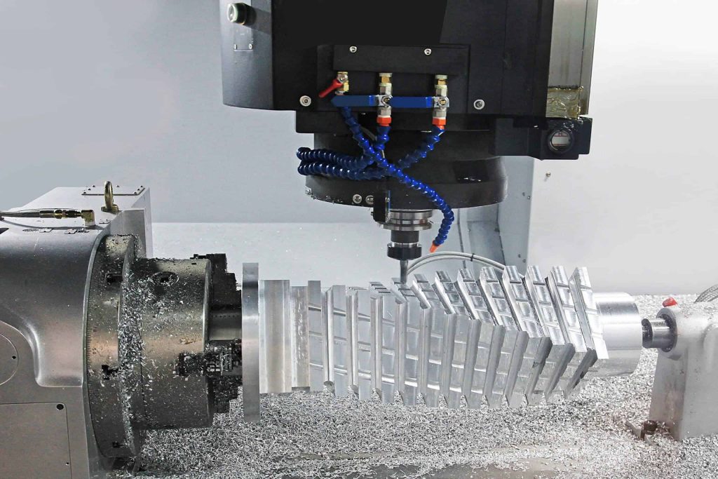
Fine machining

A machining strategy used to prioritize a finer surface on selected features.
03 fine machining cnc
ENGINEERING DOSSIER

Name the fine-machined roughness intent, toolpath and inspection surfaces

Fine machining applies to named features, not the whole part by default

Tie the finer surface to tool access, function and an inspection method.

Sequence and substrate evidence

Record the base material, preparation, operation order and any approved appearance reference so the visible result remains explainable.

Acceptance belongs to named surfaces

Use a surface map for cosmetic zones, contacts, threads, fits, masking and geometry-dependent variation.

Release inputs for Fine machining

Specify surfaces, functional purpose, reference or measurement method and edge requirements.
APPEARANCE AND FUNCTION

Appearance, function and substrate boundary for Fine machining

Tie the finer surface to tool access, function and an inspection method.
Surface texture and tool marks can affect mating, sliding and sealing interfaces. Identify the functional faces and their drawing requirements before choosing the finishing toolpath.
03 fine machining cnc
DECISION CONTROLS

Protected interfaces and acceptance controls for Fine machining

Sequence and substrate evidence

Confirm substrate alloy/grade, condition and any preparation specific to Fine machining. Compatibility must be checked against the named base material, not a generic family.

Acceptance belongs to named surfaces

Identify datum surfaces, bores, threads, seal lands and edges that must retain their specified dimensions. Define machining access and protect already-finished features during subsequent operations.

Release inputs for Fine machining

Provide the drawing revision, material grade, named surfaces, roughness parameter and limit where required, dimensional tolerances, edge treatment and inspection method.
PROJECT-SPECIFIC DECISION DATA

Finish map before Fine machining release

Confirm substrate, preparation, appearance/function, protected zones and inspection evidence; do not infer acceptance from the finish name alone.
Decision itemWhat must be resolvedEvidence at release
Name the critical machined featuresIdentify datum faces, mating bores, threads, seal lands and edges on the released drawing. Assign finer machining only where the feature function requires it.Drawing revision, feature identifiers and agreed dimensional or surface requirements.
Plan material condition and machining sequenceConfirm material grade and heat-treatment condition, stock allowance, workholding, tool access and the order of operations for the named features.Reviewed process route, setup references and inspection checkpoints.
Verify texture and dimensional conformityUse the specified surface-texture parameter and limit where required. Check critical dimensions, thread function and edge condition with the agreed measurement method.Traceable measurement results tied to the drawing and the inspected feature.
Release against measured project evidenceConfirm that the inspection plan covers the specified features and acceptance criteria. Review any appearance reference separately; a photograph does not prove roughness or dimensional conformity.Released drawing, inspection method, measured results and recorded acceptance.
Complete CNC machining RFQ package diagram showing STEP file, 2D PDF drawing, material, quantity, finish, tolerance, inspection, application, lead time and packaging
INSPECTION AND ACCEPTANCE

Inspect Fine machining against the named reference and functional interfaces

Verify the specified surface texture, critical dimensions, thread function and edge condition against the drawing. Use the agreed measurement method; a photograph alone cannot establish roughness or dimensional conformity.
Geometry, access, edges, recesses and part-to-part variation can affect the result; use a named reference and surface map.
PART AND PROCESS EVIDENCE

Fine machining close-up, process and acceptance evidence

03 fine machining cnc
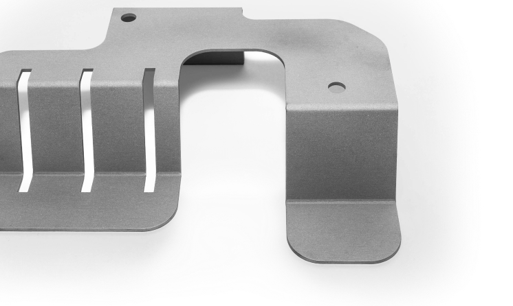
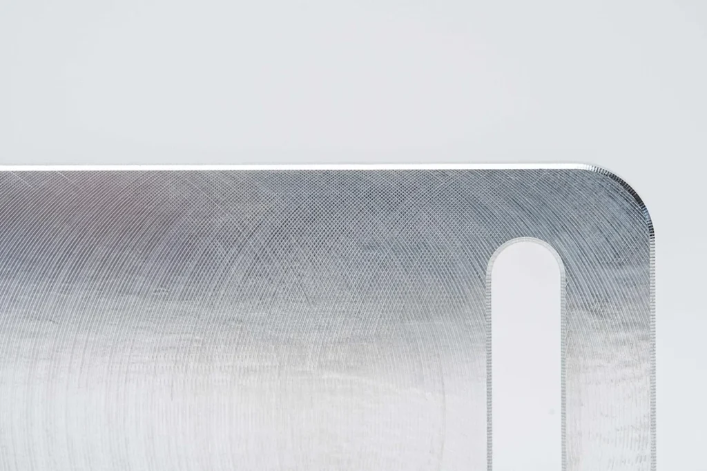
Machined metal sample showing toolpath texture and a slotted edge. Surface roughness and dimensional acceptance require the drawing and measurement results.
Complete CNC machining RFQ package diagram showing STEP file, 2D PDF drawing, material, quantity, finish, tolerance, inspection, application, lead time and packaging
Illustrative CNC review package: CAD, drawing, material and inspection inputs. This diagram is not an actual inspection report.
Premium engineering board showing CNC part diagrams, exploded callouts, tolerance zones, cross-section line, surface finish area and inspection icons
Illustrative feature-review board connecting drawing callouts and inspection locations. Final acceptance uses the project drawing and measured results.
DECISION QUESTIONS

Fine machining specification and inspection questions

What must be defined before reviewing Fine machining?

Tie the finer surface to tool access, function and an inspection method. Record the base material, preparation, operation order and any approved appearance reference so the visible result remains explainable.

Which interfaces need project-specific confirmation?

Confirm datum surfaces, mating bores, threads, seal lands and edges against the drawing. Tool access, local geometry and the machining sequence must support the specified dimensions and surface texture.

What should accompany release?

Provide the released drawing revision and the agreed inspection results for surface texture, critical dimensions, threads and edges. Include any required appearance reference without substituting it for measurement.
PROJECT BRIEF

Fine machining finish map and acceptance checklist

Use these page-specific checks to define substrate, preparation, appearance or function, protected zones and acceptance evidence for Fine machining. Do not release from the finish name alone.

Pretreatment and substrate — Fine machining applies to named features, not the whole part by default

Tie the finer surface to tool access, function and an inspection method. Record substrate and pretreatment on a controlled surface map.

Appearance or function — Sequence and substrate evidence

Record the base material, preparation, operation order and any approved appearance reference so the visible result remains explainable. Attach the named appearance or functional reference used for acceptance.

Masking and acceptance — Acceptance belongs to named surfaces

Use a surface map for cosmetic zones, contacts, threads, fits, masking and geometry-dependent variation. Mark masking, fit-sensitive zones and the inspection record required at release.
CONTINUE THE ENGINEERING REVIEW

Continue the engineering review for Fine machining

Connect this decision to the related manufacturing route, material, finish and file-review workflow.