

A successful metal additive part starts with a complete manufacturing plan, not just a printable model. Use this guide to prepare the decisions that connect SLM geometry to support removal, material condition, finished interfaces and acceptance evidence.
1. What SLM means for the part
Selective laser melting is a laser powder-bed metal additive process. A laser melts selected regions of successive powder layers to build the part. The geometry leaving the build is not necessarily the finished component: supports, powder removal, treatment, machining and inspection may still be required. Renishaw’s process overview explains the powder-bed mechanism; its equipment capabilities are not Debaolong specifications.
Separate the model used to describe the final part from the additional geometry and process choices needed to manufacture it. A drawing should identify what the customer will accept after all agreed operations, rather than treating the as-built surface as the default everywhere.
2. Identify why an additive route is being considered
Start with a functional reason: an integrated passage, a weight-saving structure, a difficult-to-machine internal feature or a component that might replace several assembled pieces. Then compare a simpler machined or fabricated version. Complexity is worthwhile only if it serves the application and can be manufactured, cleaned and checked.
For an early prototype, name the decision the part must answer. A fit model, a flow-development part and a load-bearing prototype need different evidence. Do not treat a successful visual demonstration as qualification for a different service condition.
3. Confirm the alloy and final condition
Debaolong’s confirmed SLM base families are stainless steel, titanium and aluminum. The exact grade, powder specification, treatment, traceability and suitability remain project-specific. A base-family name is not permission to substitute one alloy or material condition for another.
Put the required grade and documentation on the request, or explicitly ask for material selection help. Identify operating conditions and any governing customer specification. Supplier material data must be read with its process and treatment conditions; the EOS metal-materials overview illustrates that material and process choices are linked, not a universal property guarantee.
4. Design access into supports and enclosed features
For every cavity or channel, ask how loose powder will leave and how that result will be verified. For every supported surface, ask whether the support can be reached without damaging a critical face. An opening visible in CAD does not by itself establish a workable cleaning path.
- Provide section views of internal passages, changes in direction and blind regions.
- Mark surfaces where support contact is unacceptable.
- Review splitting, reorienting or redesigning a feature if access is unresolved.

5. Review orientation, stress and distortion together
Build orientation affects support placement and the surfaces presented to the process. Thermal history can also create residual stress and distortion. These are related planning questions, not issues to defer until the part comes off the plate. Renishaw’s DfAM essentials covers orientation, supports, surface finish and distortion.
Ask the manufacturing reviewer to identify the proposed build direction, sensitive surfaces and the sequence for treatment and separation. Record which dimensions will be checked before and after finishing. Do not prescribe one stress-relief schedule or support angle for every alloy and geometry.
6. Specify the surface after post-processing
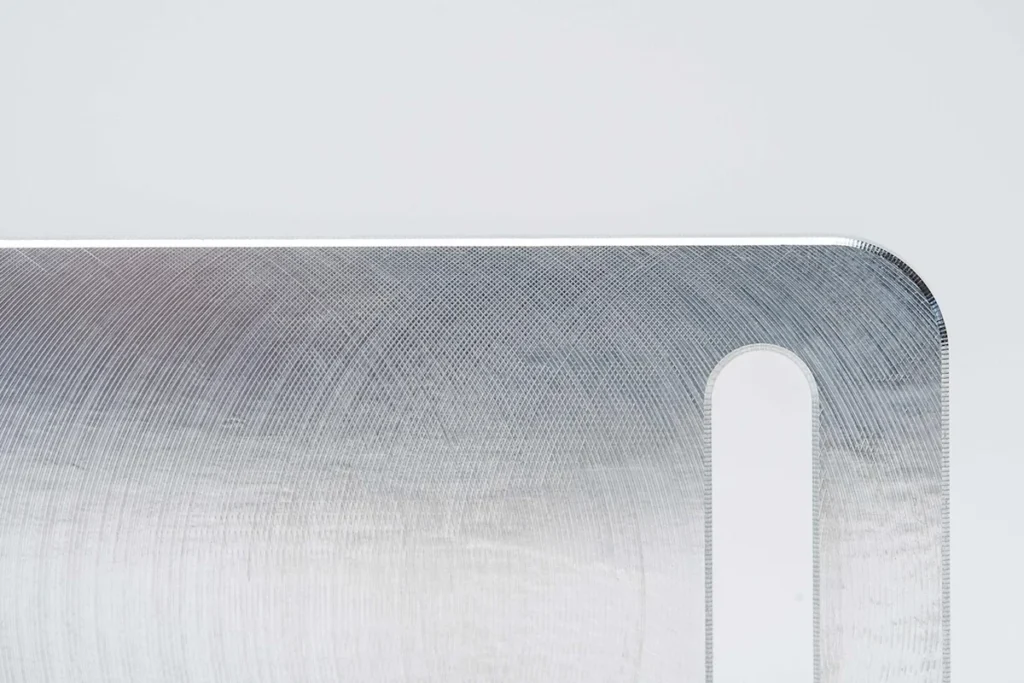
Divide the drawing into surface zones: appearance, contact, sealing, internal flow and areas where the agreed as-built condition is acceptable. State the requirement for each zone. A general instruction to make the part smooth leaves the critical surfaces undefined.
Review support removal, blasting, polishing, machining or other operations as a proposed sequence. Ask whether each operation can reach the intended zone and whether it could alter a mating dimension. Treatment and finish selection require confirmation for the chosen material; this guide does not promise every finish for every alloy.
7. Reserve a plan for interfaces and threads
Mark fitted bores, datum faces, sealing lands and threads separately from noncritical geometry. If they need machining after printing, agree the stock allowance, clamping approach and cutting-tool access before the build. Do not add a generic allowance everywhere without considering the actual setup.
| Feature | Question before build | Evidence after finishing |
|---|---|---|
| Mating bore | How will it be located, held and finished? | Size and location against agreed datums |
| Thread | Is there access for the selected finishing method? | Agreed thread acceptance check |
| Sealing face | What material may be removed and which areas are masked? | Specified geometry and surface condition |
| Internal channel | How will powder removal and access be demonstrated? | Agreed cleanliness or functional check |
8. Define inspection before it becomes a surprise
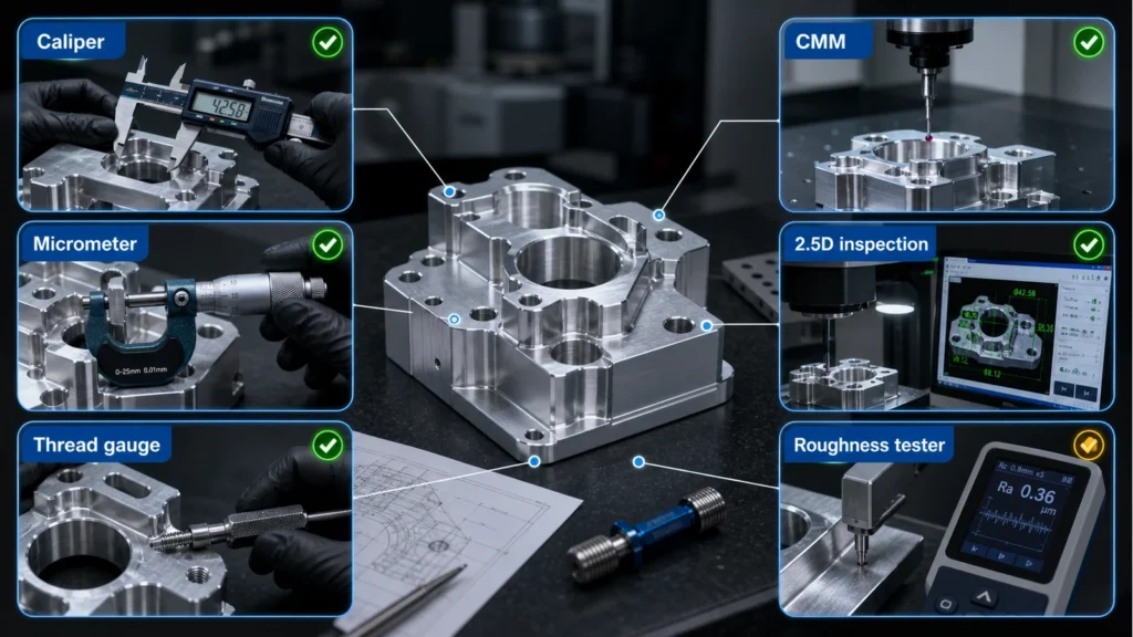
List the characteristics that decide whether the part is acceptable, then agree a method for each. Visible appearance, dimensional conformance, internal features and material requirements are different questions. A scan of the outside cannot establish every internal or material requirement.
Where internal quality is critical, discuss suitable evaluation and its limitations before quoting. NIST’s review of monitoring and non-destructive evaluation treats these as distinct parts of the metal-additive quality problem. No particular inspection method or certification is promised here.
9. Carry prototype learning into repeat production
Capture the accepted drawing revision, material condition, orientation rationale, finishing sequence and inspection record from the prototype. Identify what changes before the next batch: geometry, quantity, supplier setup or acceptance criteria. Repeated part names do not guarantee an unchanged manufacturing plan.
Use a first-article review where appropriate to the project. Record deviations and their disposition, and confirm which lessons are incorporated into the released drawing. Medical, aerospace or other regulated uses need their own project-specific qualification and documentation review.
10. Compare SLM with conventional and polymer routes
| Route to compare | When it deserves a review | Question to resolve |
|---|---|---|
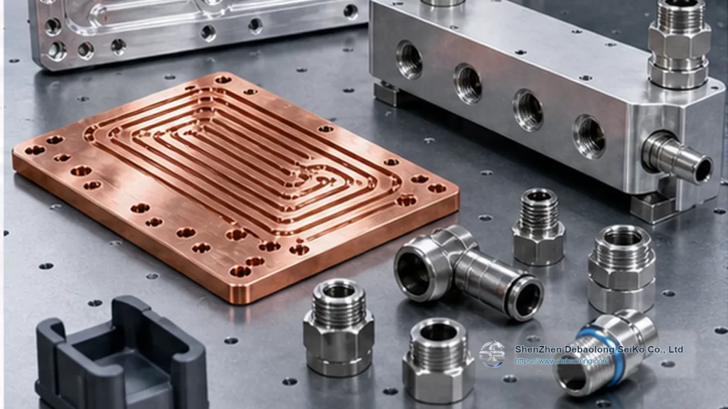
| CNC machining | Accessible geometry and important fitted interfaces | Can a stock-based part meet the function with fewer operations? |
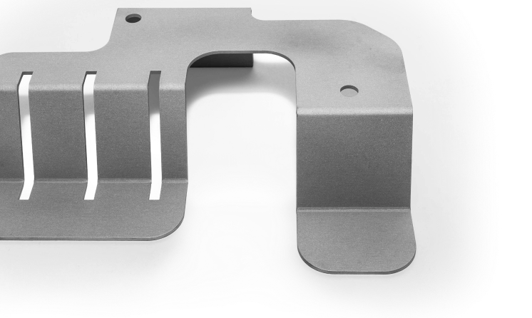
| Sheet metal | Enclosures, guards and structures made from sheet | Can bends and joints replace unnecessary solid geometry? |
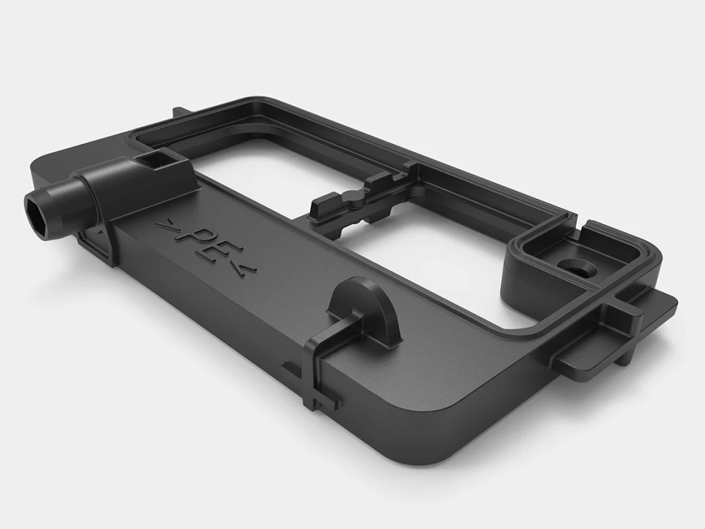
| Polymer additive | Form, assembly or selected functional prototypes | Does the evaluation actually require metal behavior? |
| SLM | Metal geometry that justifies an additive build | Are access, post-processing and acceptance feasible? |
11. Send a reviewable SLM request
- Controlled CAD and drawing revision, with quantity and intended use.
- Required alloy and condition, or the material decision that remains open.
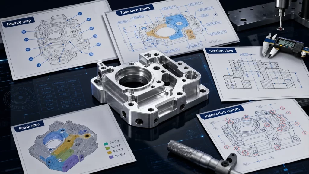
- Critical surfaces, dimensions, datums, interfaces and internal passages.
- Areas where supports or visible witness marks are unacceptable.
- Finish zones and any planned assembly or post-machining operation.
- Inspection, traceability and application-specific documentation requirements.
Use Upload CAD to start the existing project-review workflow, or contact Debaolong if the manufacturing route is still undecided. A request begins a review; it is not automatic confirmation of manufacturability or a production commitment.
12. Continue with the connected manufacturing decisions
Review the SLM capability, compare the five additive processes, and check 3D-printing material families. Connect surface requirements to finish options and compare CNC machining or sheet metal fabrication where the geometry suggests an alternative.