Engineering review for every RFQ
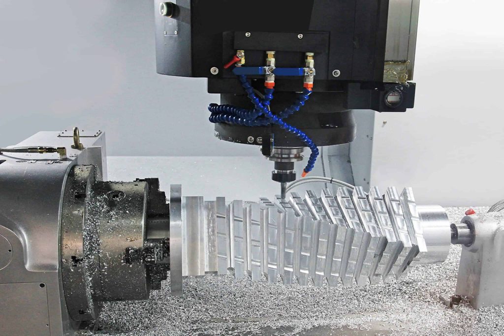
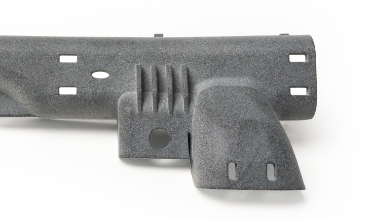
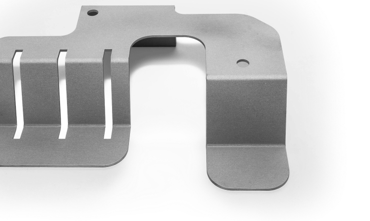
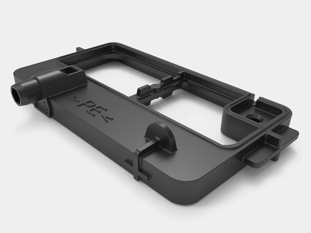
CNC · 3D Printing · Sheet Metal · Injection Molding
Prototype · Low Volume · Production
Process, material, finish and inspection decisions connected

Shenzhen, China

Search
Menu

A practical manufacturing partner connecting process, materials, applications and review.

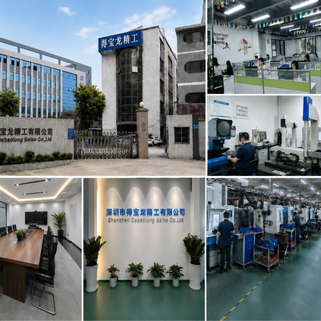
The factory collage shows building, workshop and manufacturing context.

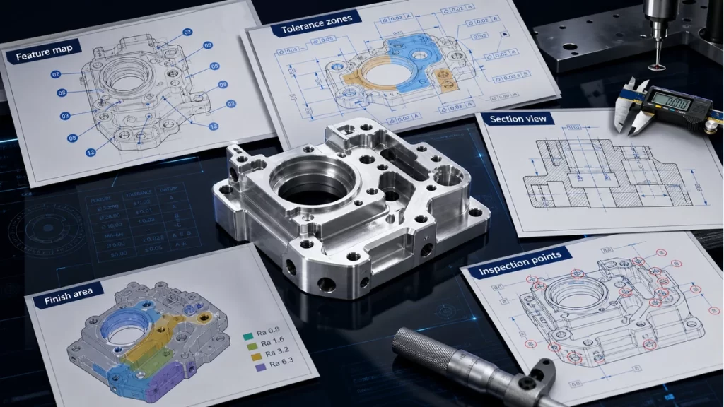
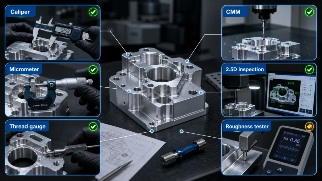
An illustrative planning graphic connects critical features, manufacturing decisions and engineering review. It is not a production inspection record.

Use Contact for general conversation or Engineering Review for a project-specific brief.
METAL ADDITIVE MANUFACTURING

SLM Metal 3D Printing

Use SLM when metal powder-bed fusion creates value through complex internal geometry, weight reduction or integrated features that are difficult to produce conventionally.
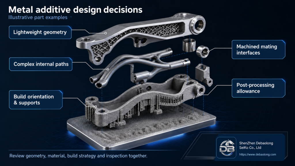
Illustration of metal additive design choices: lattice bracket, internal passages, build supports, mating interfaces and machining allowance.
ENGINEERING DOSSIER

Decide what metal additive makes possible for this part

Geometry that justifies the build

Compare integrated passages, weight-saving structures and consolidated components with a machined or assembled alternative. Complexity is useful only when it serves the part function.

Support and powder access

Review how supports will be reached and removed, where powder can escape and which internal features can be inspected. Enclosed geometry needs a cleaning and verification plan.

Material and final condition

Aluminum, stainless steel and titanium are the base families for review. Confirm the exact alloy, powder specification, heat treatment and required material records for the project.

Interfaces after the build

Separate as-built areas from threads, bores, sealing faces and datum features that need further work. Plan machining allowance, access, surface treatment and final checks together.
MANUFACTURING ROUTE

Plan the complete route, from build orientation to inspected part

Review support access, overhangs, enclosed powder paths, wall transitions, orientation, datum strategy and the stock required on critical interfaces.
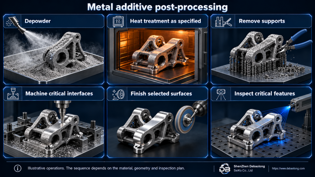
Confirm part intent, material and build strategy, then plan powder removal, heat treatment, plate and support removal, machining, surface finishing and inspection together. The operation sequence depends on the alloy, geometry and project requirements.
Illustrated metal additive post-processing operations: depowdering, specified heat treatment, support removal, critical-interface machining, surface finishing and inspection.
DECISION CONTROLS

Define acceptance before committing the build

Geometry review

CAD, orientation priorities, support access and powder-removal paths.

Material record

Named alloy, required condition and project-specific traceability.

Interface checks

Drawing datums, post-machined features, finish zones and inspection method.
PROJECT-SPECIFIC DECISION DATA

Bring these decisions into the SLM quotation brief

Use the drawing to distinguish required performance from choices that are still open. Dimensions, build limits and material properties need project-specific confirmation.
DecisionResolve before quotingUseful input
Build and accessSupport contact, powder removal and inspection accessCAD views and sections
Material conditionExact alloy, required treatment and documentationMaterial specification
Critical interfacesMachining allowance, datums, threads and fit surfacesControlled drawing
Finish and acceptanceSurface zones, masking and final checksInspection and finish notes
PART AND PROCESS EVIDENCE

Metal additive geometry and post-processing context

Illustration of metal additive design choices: lattice bracket, internal passages, build supports, mating interfaces and machining allowance.
Illustrative metal additive design choices: geometry, supports, mating interfaces and machining allowance. Not a production or inspection record.
Illustrated metal additive post-processing operations: depowdering, specified heat treatment, support removal, critical-interface machining, surface finishing and inspection.
Illustrative post-processing operations. The sequence depends on material, part geometry and the inspection plan.
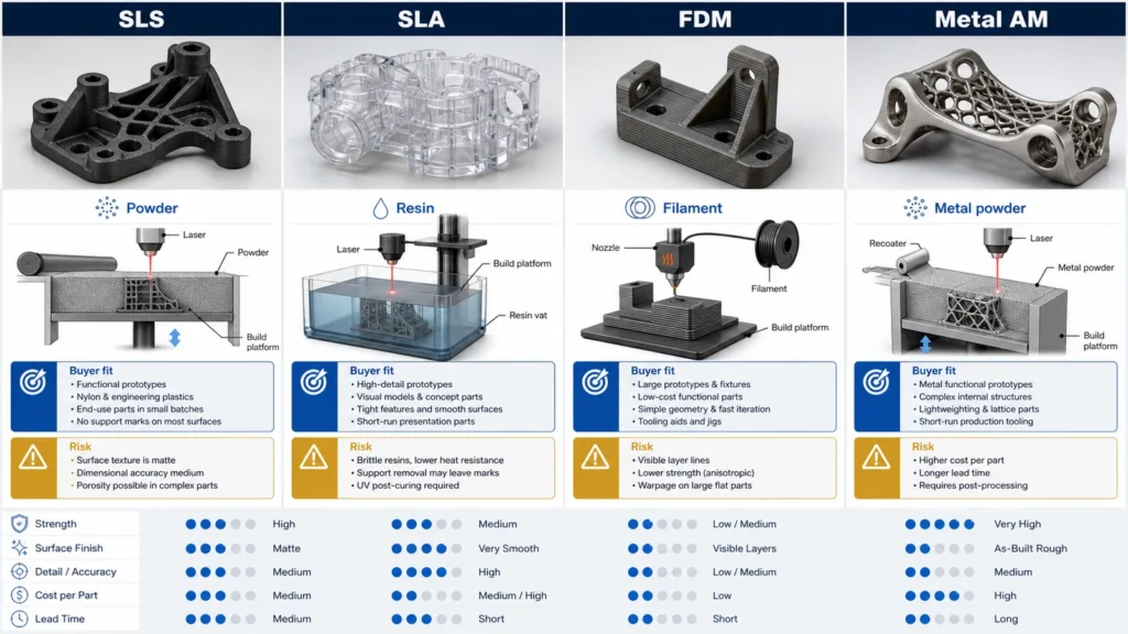
Engineering comparison diagram of SLS, SLA, FDM and metal 3D printing processes for prototype sourcing decisions
Compare polymer and metal additive routes before committing the build process.
DECISION QUESTIONS

SLM material, interface and quotation questions

Which material families are currently confirmed for SLM review?

Aluminum, stainless steel and titanium base families. The exact alloy, powder condition and supporting evidence are confirmed per project.

Which features usually need post-machining?

Critical bores, sealing faces, threads, bearing seats, datums and tight-fit interfaces commonly require planned stock and post-machining.

What should an SLM RFQ include?

Share CAD, drawing, quantity, base material intent, critical interfaces, surface requirements and the inspection evidence the application needs.
PROJECT BRIEF

A focused SLM project brief

Connect the intended part function with build constraints and the checks needed after finishing.

Part purpose and alternatives

Explain whether the part is a prototype, fixture, lightweight component or integrated flow geometry. State why an additive route is being considered.

Critical surfaces and features

Mark sealing faces, fitted bores, threads and inaccessible cavities. Include a drawing and identify the features that must be machined or measured after the build.

Material and quantity

State the preferred base family, exact grade if specified, quantity and required material or inspection documentation. Keep unresolved requirements explicit.