Engineering review for every RFQ
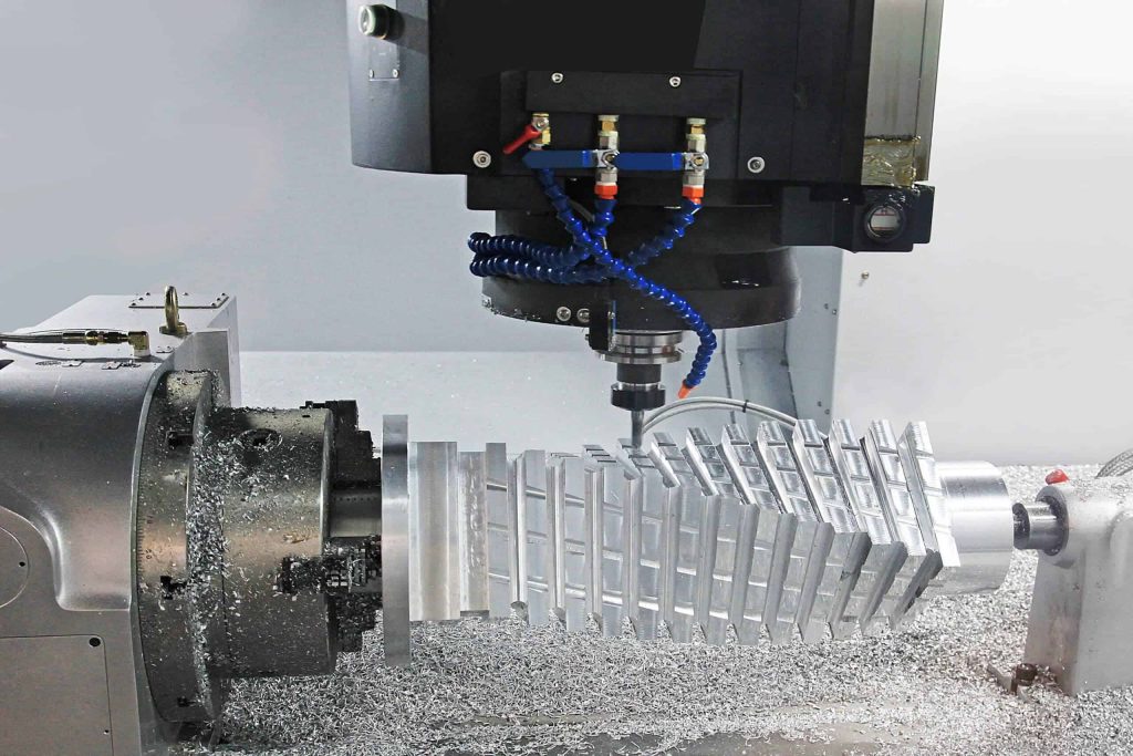
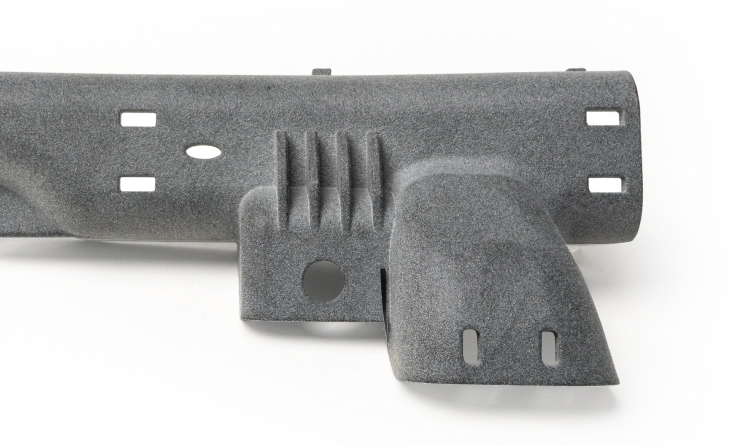
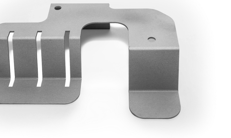
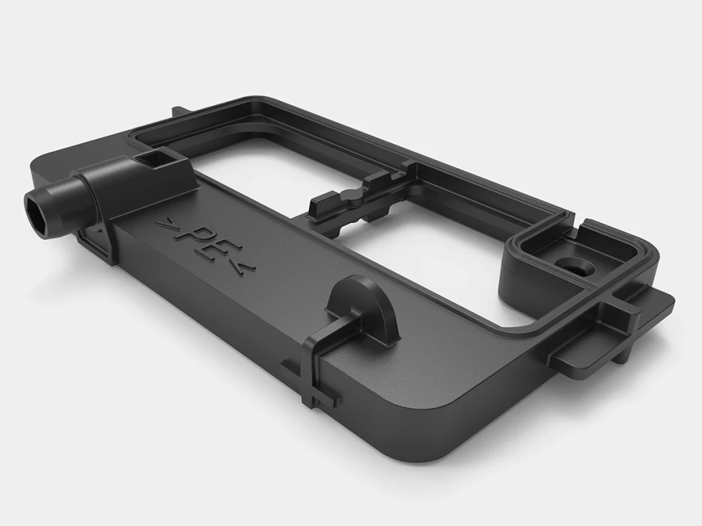
CNC · 3D Printing · Sheet Metal · Injection Molding
Prototype · Low Volume · Production
Process, material, finish and inspection decisions connected

Shenzhen, China

Search
Menu

A practical manufacturing partner connecting process, materials, applications and review.

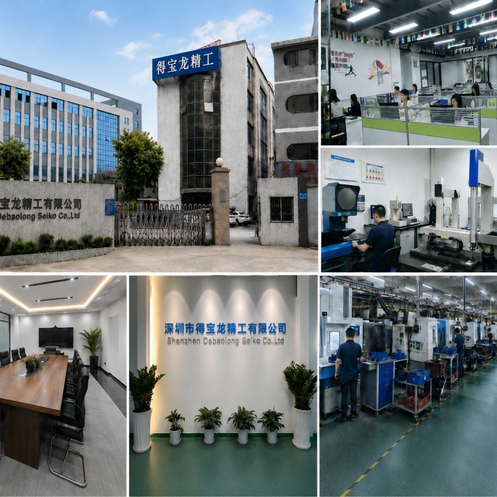
The factory collage shows building, workshop and manufacturing context.

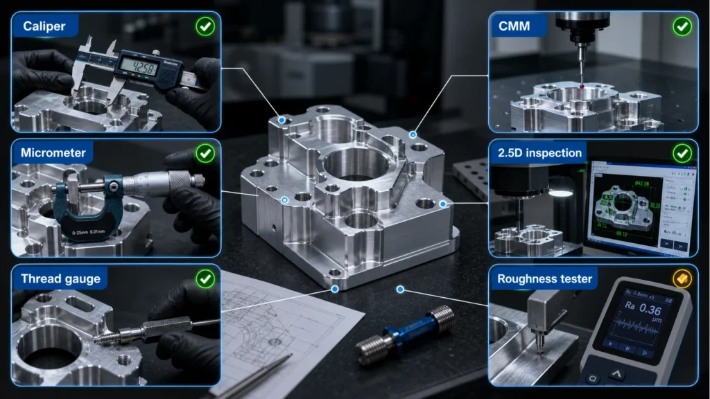
An illustrative planning graphic connects critical features, manufacturing decisions and engineering review. It is not a production inspection record.

Use Contact for general conversation or Engineering Review for a project-specific brief.

MOLDING

Overmolding

Overmolding adds a molded material or stage around a substrate and depends on the interface between them.
Debaolong injection molding services (3)
ENGINEERING DOSSIER

Protect substrate, bond interface, sealing and two-stage acceptance in overmolding

Substrate and overmold sequence

Define the first-stage part, handling condition and where the second material begins and ends.

Bond and mechanical retention intent

State whether adhesion, geometry or both create the required interface, without assuming universal compatibility.

Sealing and cosmetic boundaries

Protect edges, openings and surfaces where flash, witness or material transition matters.

Two-stage acceptance

Inspect the substrate, overmold coverage and the final functional interface as connected evidence.
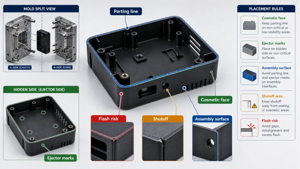
Diagram of molded plastic part showing parting line, ejector marks, slider risk, flash risk, assembly surface and cosmetic face
MANUFACTURING ROUTE

Route logic for Overmolding

Define the first-stage part, handling condition and where the second material begins and ends. Protect edges, openings and surfaces where flash, witness or material transition matters.
State whether adhesion, geometry or both create the required interface, without assuming universal compatibility. Best input: Both stages and the interface map.
DECISION CONTROLS

Release controls specific to Overmolding

Best input

Both stages and the interface map

Key risk

Material compatibility and boundary control

Release evidence

Coverage, bond intent and final fit
PROJECT-SPECIFIC DECISION DATA

Decision record before Overmolding release

Use this table to connect the process decision to the CAD, drawing and inspection evidence. Values remain project-specific until reviewed.
Decision itemWhat must be resolvedEvidence at release
Substrate and overmold sequenceDefine the first-stage part, handling condition and where the second material begins and ends.Both stages and the interface map
Bond and mechanical retention intentState whether adhesion, geometry or both create the required interface, without assuming universal compatibility.Material compatibility and boundary control
Sealing and cosmetic boundariesProtect edges, openings and surfaces where flash, witness or material transition matters.Coverage, bond intent and final fit
Two-stage acceptanceInspect the substrate, overmold coverage and the final functional interface as connected evidence.Coverage, bond intent and final fit
PART AND PROCESS EVIDENCE

Overmolding process, interface and inspection evidence

Debaolong injection molding services (3)
Debaolong _injection molding services (3)
Vacuum casting material and overmolding review infographic showing silicone mold planning, wall thickness, undercuts, inserts, overmolding, surface finish, and prototype accuracy risk.
Diagram of molded plastic part showing parting line, ejector marks, slider risk, flash risk, assembly surface and cosmetic face
DECISION QUESTIONS

Overmolding route and release questions

What must be defined before reviewing Overmolding?

Define the first-stage part, handling condition and where the second material begins and ends. State whether adhesion, geometry or both create the required interface, without assuming universal compatibility.

Which interfaces need project-specific confirmation?

Protect edges, openings and surfaces where flash, witness or material transition matters. Escalate Material compatibility and boundary control and any geometry, access, material or interface requirement that the drawing does not resolve.

What should accompany release?

Inspect the substrate, overmold coverage and the final functional interface as connected evidence. Coverage, bond intent and final fit
PROJECT BRIEF

Overmolding project brief and release checklist

Use these page-specific checks to turn the Overmolding route into reviewable CAD, drawing and inspection inputs.

Geometry and route input — Substrate and overmold sequence

Define the first-stage part, handling condition and where the second material begins and ends. Include the relevant CAD orientation, interfaces and quantity in the review brief.

Release evidence — Bond and mechanical retention intent

State whether adhesion, geometry or both create the required interface, without assuming universal compatibility. Name the drawing dimensions and inspection evidence required at release.

RFQ handoff — Sealing and cosmetic boundaries

Protect edges, openings and surfaces where flash, witness or material transition matters. Upload controlled CAD/drawing inputs and state the unresolved route decision.
CONTINUE THE ENGINEERING REVIEW

Continue the engineering review for Overmolding

Connect this decision to the related manufacturing route, material, finish and file-review workflow.