Engineering review for every RFQ
CNC · 3D Printing · Sheet Metal · Injection Molding
Prototype · Low Volume · Production
Process, material, finish and inspection decisions connected

Shenzhen, China

Search
Menu

A practical manufacturing partner connecting process, materials, applications and review.

The factory collage shows building, workshop and manufacturing context.

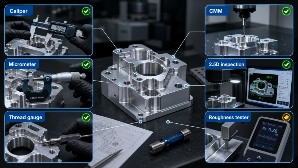
An illustrative planning graphic connects critical features, manufacturing decisions and engineering review. It is not a production inspection record.

Use Contact for general conversation or Engineering Review for a project-specific brief.

SHEET

Bending

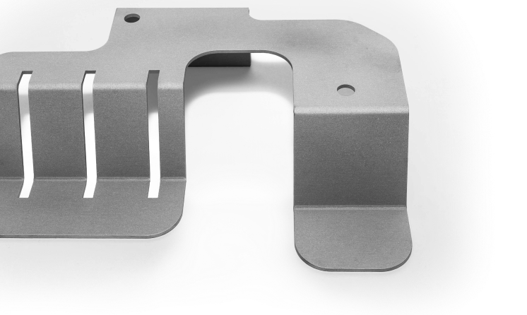
Bending forms sheet components around material, thickness, bend direction and tooling access.
debaolong Bending2
ENGINEERING DOSSIER

Carry bend intent from the flat pattern into the inspected formed part

Flat-to-formed intent

Show material and thickness, bend direction, radii and which dimensions apply after forming.

Features near bends

Review holes, slots, tabs and reliefs against deformation, tooling access and the intended formed datum.

Sequence and tool access

Multiple bends can block later operations; identify which faces and hardware must remain accessible.

Accept the formed state

Inspect angles, flange relationships, datums and assembly interfaces on the part in its useful condition.
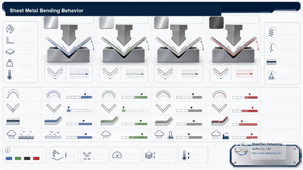
Sheet metal bending behavior diagram showing bend radius, grain direction, springback, crack risk, coating behavior and corrosion exposure.
MANUFACTURING ROUTE

Route logic for Bending

Bending converts a released flat pattern through a planned press-brake sequence. Material condition, grain direction, tooling, bend order and springback compensation must be resolved together.
Define inside radius, bend angle, flange length, reliefs, hole-to-bend distance, grain direction and tool access without treating the flat pattern as the finished part.
DECISION CONTROLS

Release controls specific to Bending

Best input

Flat and formed definition

Key risk

Sequence, springback and access

Release evidence

Formed geometry and assembly fit
PROJECT-SPECIFIC DECISION DATA

Decision record before Bending release

Use this table to connect the process decision to the CAD, drawing and inspection evidence. Values remain project-specific until reviewed.
Decision itemWhat must be resolvedEvidence at release
Flat-to-formed intentShow material and thickness, bend direction, radii and which dimensions apply after forming.Flat and formed definition
Features near bendsReview holes, slots, tabs and reliefs against deformation, tooling access and the intended formed datum.Sequence, springback and access
Sequence and tool accessMultiple bends can block later operations; identify which faces and hardware must remain accessible.Formed geometry and assembly fit
Accept the formed stateInspect angles, flange relationships, datums and assembly interfaces on the part in its useful condition.Formed geometry and assembly fit
PART AND PROCESS EVIDENCE

Bending process, interface and inspection evidence

debaolong Bending2
debaolong Bending2
Sheet metal bending behavior diagram showing bend radius, grain direction, springback, crack risk, coating behavior and corrosion exposure.
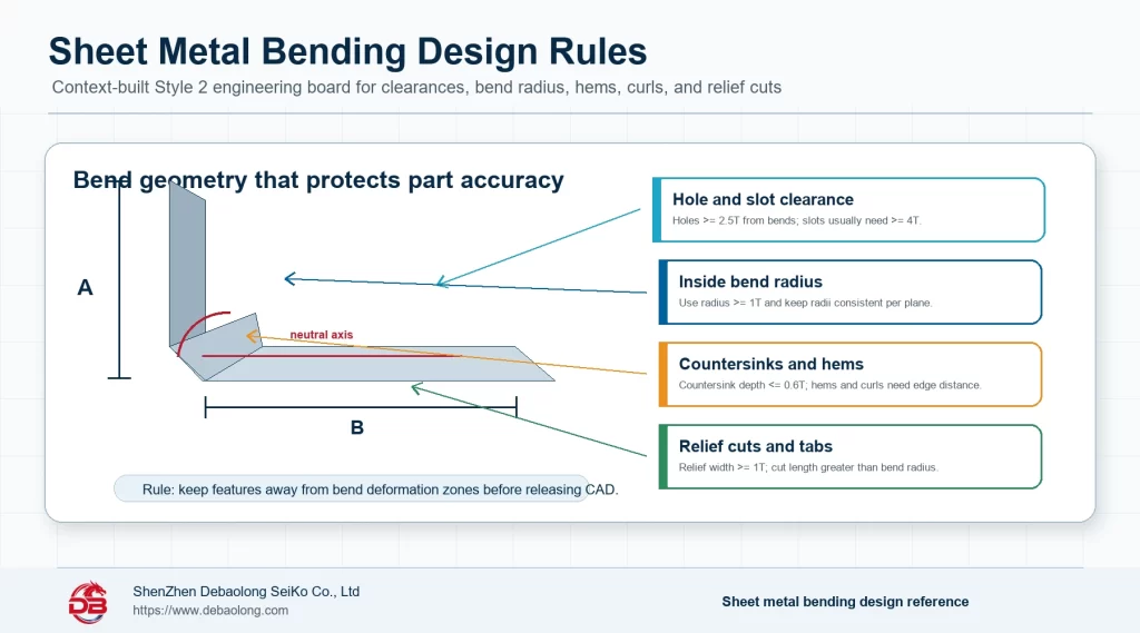
Sheet metal bending design rules infographic showing bend radius, hole and slot clearance, countersink spacing, hems, tabs, and relief cuts.
DECISION QUESTIONS

Bending route and release questions

What must be defined before reviewing Bending?

Show material and thickness, bend direction, radii and which dimensions apply after forming. Review holes, slots, tabs and reliefs against deformation, tooling access and the intended formed datum.

Which interfaces need project-specific confirmation?

Multiple bends can block later operations; identify which faces and hardware must remain accessible. Escalate Sequence, springback and access and any geometry, access, material or interface requirement that the drawing does not resolve.

What should accompany release?

Inspect angles, flange relationships, datums and assembly interfaces on the part in its useful condition. Formed geometry and assembly fit
PROJECT BRIEF

Bending project brief and release checklist

Use these page-specific checks to turn the Bending route into reviewable CAD, drawing and inspection inputs.

Geometry and route input — Flat-to-formed intent

Show material and thickness, bend direction, radii and which dimensions apply after forming. Include the relevant CAD orientation, interfaces and quantity in the review brief.

Release evidence — Features near bends

Review holes, slots, tabs and reliefs against deformation, tooling access and the intended formed datum. Name the drawing dimensions and inspection evidence required at release.

RFQ handoff — Sequence and tool access

Multiple bends can block later operations; identify which faces and hardware must remain accessible. Upload controlled CAD/drawing inputs and state the unresolved route decision.