Engineering review for every RFQ
CNC · 3D Printing · Sheet Metal · Injection Molding
Prototype · Low Volume · Production
Process, material, finish and inspection decisions connected

Shenzhen, China

Search
Menu

A practical manufacturing partner connecting process, materials, applications and review.

The factory collage shows building, workshop and manufacturing context.

An illustrative planning graphic connects critical features, manufacturing decisions and engineering review. It is not a production inspection record.


Use Contact for general conversation or Engineering Review for a project-specific brief.

MECHANICAL

Polishing

Progressive surface refinement changes appearance and touch condition on accessible areas.
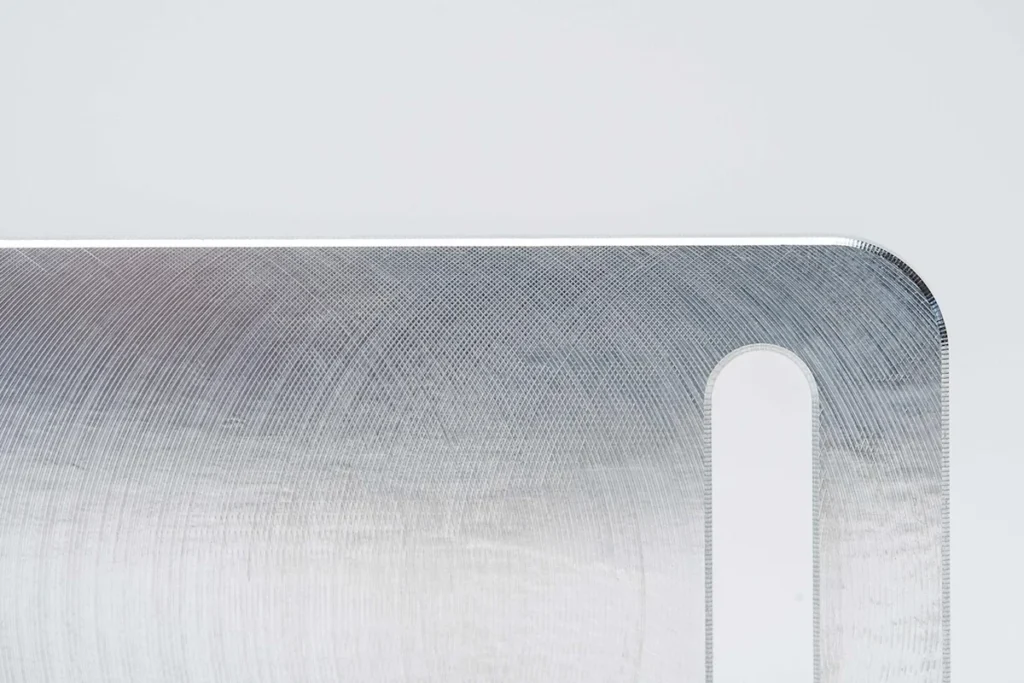
Close-up of a reflective polished metal corner
ENGINEERING DOSSIER

Define polish direction, starting condition, reflection target and edge protection

Polishing changes edges as well as appearance

Protect geometry and datums while defining access, direction and the final visual reference.

Sequence and substrate evidence

Record the base material, preparation, operation order and any approved appearance reference so the visible result remains explainable.

Acceptance belongs to named surfaces

Use a surface map for cosmetic zones, contacts, threads, fits, masking and geometry-dependent variation.

Release inputs for Polishing

Specify base material, polished zones, target reference, edge preservation and protected features.
Close-up of a reflective polished metal corner
APPEARANCE AND FUNCTION

Appearance, function and substrate boundary for Polishing

Protect geometry and datums while defining access, direction and the final visual reference.
Function: Protection, contact, wear or interface role. Use a surface map for cosmetic zones, contacts, threads, fits, masking and geometry-dependent variation.
DECISION CONTROLS

Protected interfaces and acceptance controls for Polishing

Sequence and substrate evidence

Confirm substrate alloy/grade, condition and any preparation specific to Polishing. Compatibility must be checked against the named base material, not a generic family.

Acceptance belongs to named surfaces

Map cosmetic zones, datums, fits, threads, electrical contacts, seal lands and areas that must remain uncoated or require controlled build for Polishing.

Release inputs for Polishing

Specify Polishing by process/standard where applicable, appearance reference, coverage, masking map, thickness or build requirement if relevant, and protected critical dimensions.
PROJECT-SPECIFIC DECISION DATA

Finish map before Polishing release

Confirm substrate, preparation, appearance/function, protected zones and inspection evidence; do not infer acceptance from the finish name alone.
Decision itemWhat must be resolvedEvidence at release
Polishing changes edges as well as appearanceProtect geometry and datums while defining access, direction and the final visual reference.Reference, texture, color or toolpath
Sequence and substrate evidenceRecord the base material, preparation, operation order and any approved appearance reference so the visible result remains explainable.Protection, contact, wear or interface role
Acceptance belongs to named surfacesUse a surface map for cosmetic zones, contacts, threads, fits, masking and geometry-dependent variation.Coverage, masking and critical features
Release inputs for PolishingSpecify base material, polished zones, target reference, edge preservation and protected features.Coverage, masking and critical features
INSPECTION AND ACCEPTANCE

Inspect Polishing against the named reference and functional interfaces

Inspect Polishing against the agreed sample/reference, coverage and surface zones; verify masked interfaces, thread function, fit-sensitive dimensions and any required adhesion/corrosion evidence.
Geometry, access, edges, recesses and part-to-part variation can affect the result; use a named reference and surface map.
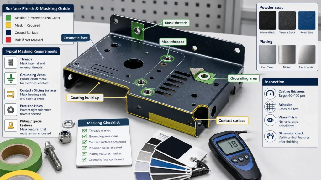
Surface finish masking diagram for sheet metal parts showing powder coating, plating, masked threads and grounding areas
PART AND PROCESS EVIDENCE

Polishing close-up, process and acceptance evidence

Close-up of a reflective polished metal corner
polishing
Surface finish masking diagram for sheet metal parts showing powder coating, plating, masked threads and grounding areas
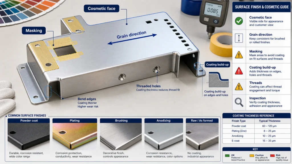
Surface finish diagram for sheet metal parts showing cosmetic face, grain direction, masking, brushed finish, plating and powder coating
DECISION QUESTIONS

Polishing specification and inspection questions

What must be defined before reviewing Polishing?

Protect geometry and datums while defining access, direction and the final visual reference. Record the base material, preparation, operation order and any approved appearance reference so the visible result remains explainable.

Which interfaces need project-specific confirmation?

Use a surface map for cosmetic zones, contacts, threads, fits, masking and geometry-dependent variation. Geometry, access, edges, recesses and part-to-part variation can affect the result; use a named reference and surface map.

What should accompany release?

Specify base material, polished zones, target reference, edge preservation and protected features. Coverage, masking and critical features
PROJECT BRIEF

Polishing finish map and acceptance checklist

Use these page-specific checks to define substrate, preparation, appearance or function, protected zones and acceptance evidence for Polishing. Do not release from the finish name alone.

Pretreatment and substrate — Polishing changes edges as well as appearance

Protect geometry and datums while defining access, direction and the final visual reference. Record substrate and pretreatment on a controlled surface map.

Appearance or function — Sequence and substrate evidence

Record the base material, preparation, operation order and any approved appearance reference so the visible result remains explainable. Attach the named appearance or functional reference used for acceptance.

Masking and acceptance — Acceptance belongs to named surfaces

Use a surface map for cosmetic zones, contacts, threads, fits, masking and geometry-dependent variation. Mark masking, fit-sensitive zones and the inspection record required at release.