Engineering review for every RFQ
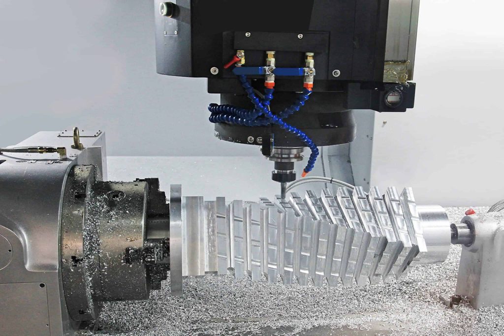
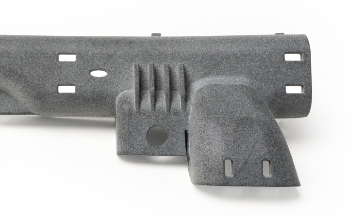
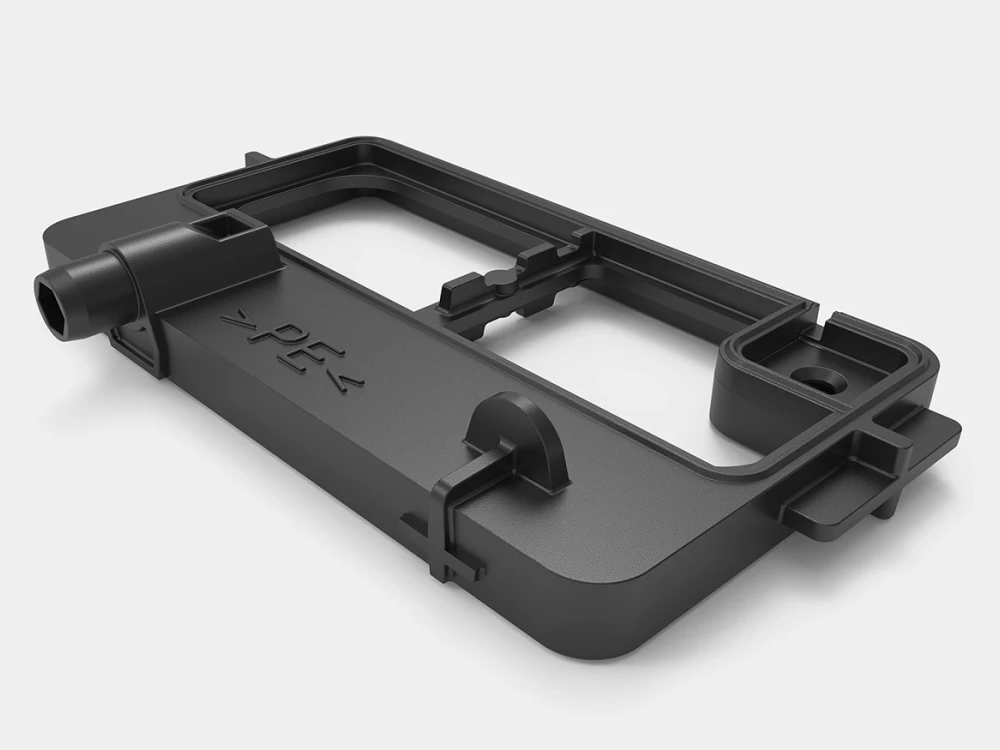
CNC · 3D Printing · Sheet Metal · Injection Molding
Prototype · Low Volume · Production
Process, material, finish and inspection decisions connected

Shenzhen, China

Search
Menu

A practical manufacturing partner connecting process, materials, applications and review.

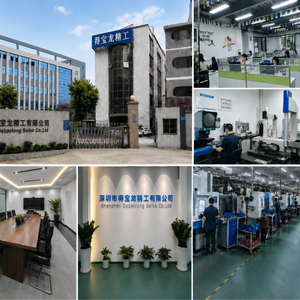
The factory collage shows building, workshop and manufacturing context.

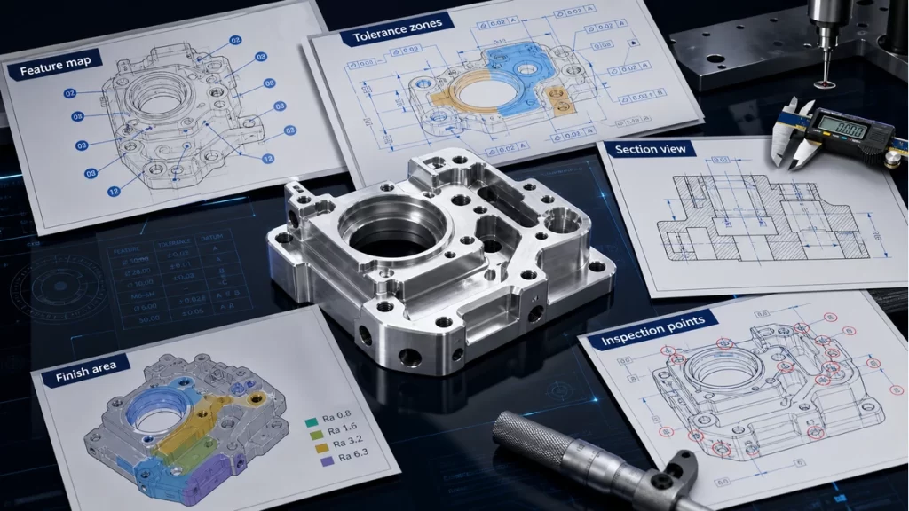
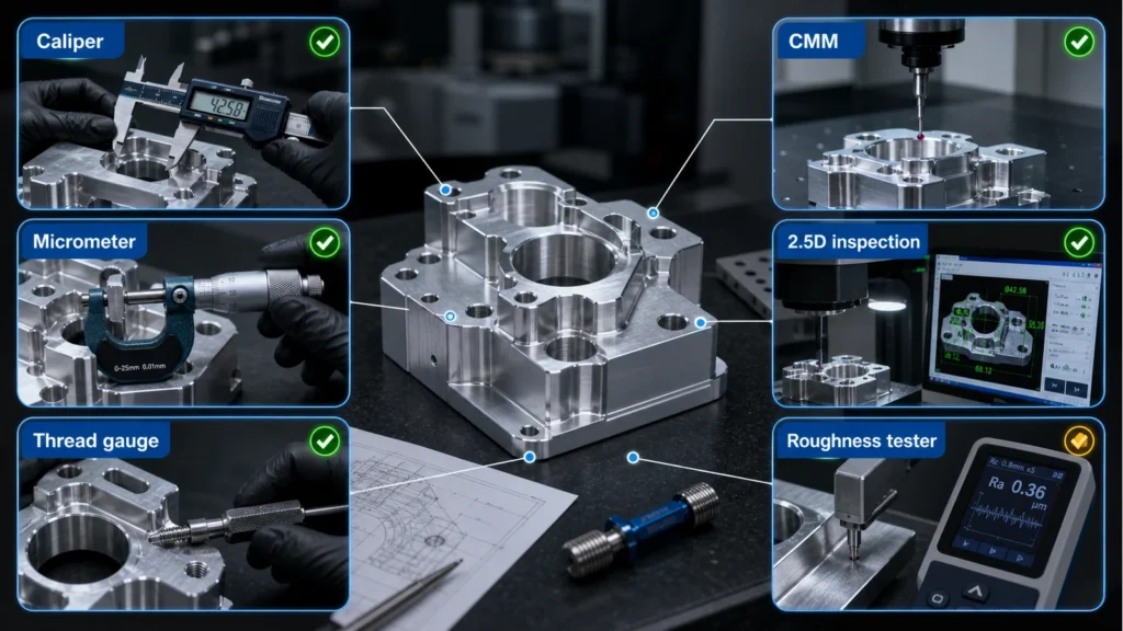
An illustrative planning graphic connects critical features, manufacturing decisions and engineering review. It is not a production inspection record.

Use Contact for general conversation or Engineering Review for a project-specific brief.
SHEET

Laser cutting

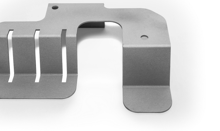
Laser cutting creates flat profiles that often continue into bending, hardware insertion, joining or finishing.
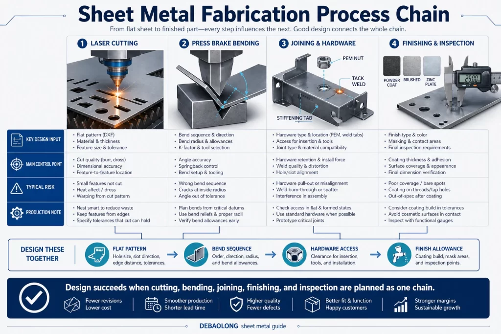
Sheet metal fabrication process chain infographic comparing laser cutting, punching, bending, welding, finishing, inspection, and release steps for production-ready parts.
ENGINEERING DOSSIER

Connect profile, edge condition, heat effect and downstream forming before laser cutting

Profile and edge intent

Separate cosmetic edges, weld edges, formed features and functional cutouts so acceptance follows the part purpose.

Material and sheet condition

Specify material, thickness and any directional or protected surface requirement before nesting and cutting.

Heat, kerf and small features

Review narrow webs, corner detail and closely spaced features in the context of the selected sheet and later forming.

From cut blank to finished part

Inspection should connect the profile to bend, hardware and assembly datums rather than stopping at a flat outline.
Procurement review board for custom sheet metal parts showing material, thickness, bend, weld, hardware, finish and inspection checks
MANUFACTURING ROUTE

Route logic for Laser cutting

Laser cutting begins with a controlled flat pattern, material/thickness confirmation, kerf and edge-quality expectations, then secondary deburr, hardware, forming, welding and finish where required.
Define sharp internal features, pierce-sensitive geometry, minimum web/slot size, cut-edge acceptance, nesting direction and the relationship to later bends.
DECISION CONTROLS

Release controls specific to Laser cutting

Best input

Flat pattern with material and thickness

Key risk

Feature scale and downstream deformation

Release evidence

Profile, edge and datum readiness
PROJECT-SPECIFIC DECISION DATA

Decision record before Laser cutting release

Use this table to connect the process decision to the CAD, drawing and inspection evidence. Values remain project-specific until reviewed.
Decision itemWhat must be resolvedEvidence at release
Profile and edge intentSeparate cosmetic edges, weld edges, formed features and functional cutouts so acceptance follows the part purpose.Flat pattern with material and thickness
Material and sheet conditionSpecify material, thickness and any directional or protected surface requirement before nesting and cutting.Feature scale and downstream deformation
Heat, kerf and small featuresReview narrow webs, corner detail and closely spaced features in the context of the selected sheet and later forming.Profile, edge and datum readiness
From cut blank to finished partInspection should connect the profile to bend, hardware and assembly datums rather than stopping at a flat outline.Profile, edge and datum readiness
PART AND PROCESS EVIDENCE

Laser cutting process, interface and inspection evidence

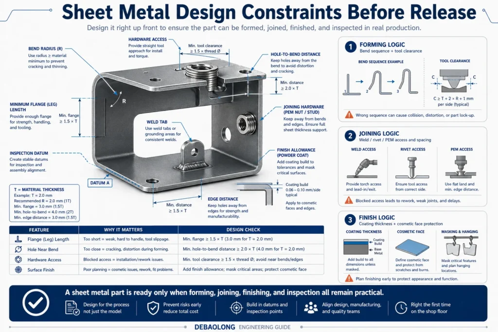
Sheet metal design constraints infographic showing bend radius, flange length, hole spacing, bend relief, hardware clearance, surface finish, and inspection planning before release.
Illustrative design checks linking cut features to forming, joining and finish access. Confirm dimensions and clearances against the actual material, tooling and drawing.
Procurement review board for custom sheet metal parts showing material, thickness, bend, weld, hardware, finish and inspection checks
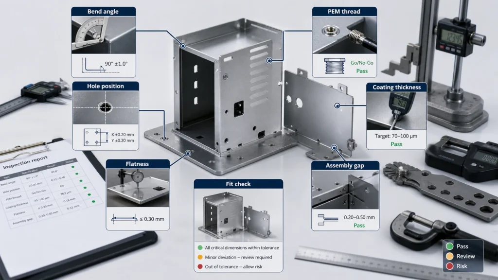
Inspection diagram for sheet metal enclosure showing bend angle, hole position, PEM thread, coating thickness, flatness and assembly gap checks
DECISION QUESTIONS

Laser cutting route and release questions

What should I send for a laser-cut part that will be bent?

Provide the flat pattern and formed-part drawing with material, sheet thickness, quantity and revision. Mark the bend relationship to holes, cutouts and assembly datums. Distinguish cosmetic, weld and functional edges, and identify protected surfaces or nesting direction where they matter. Include downstream hardware, joining and finish requirements so the cut blank can be reviewed as part of the finished component.

Which interfaces need project-specific confirmation?

Review narrow webs, corner detail and closely spaced features in the context of the selected sheet and later forming. Escalate Feature scale and downstream deformation and any geometry, access, material or interface requirement that the drawing does not resolve.

What should accompany release?

Inspection should connect the profile to bend, hardware and assembly datums rather than stopping at a flat outline. Profile, edge and datum readiness
PROJECT BRIEF

Laser cutting project brief and release checklist

Use these page-specific checks to turn the Laser cutting route into reviewable CAD, drawing and inspection inputs.

Geometry and route input — Profile and edge intent

Separate cosmetic edges, weld edges, formed features and functional cutouts so acceptance follows the part purpose. Include the relevant CAD orientation, interfaces and quantity in the review brief.

Release evidence — Material and sheet condition

Specify material, thickness and any directional or protected surface requirement before nesting and cutting. Name the drawing dimensions and inspection evidence required at release.

RFQ handoff — Heat, kerf and small features

Review narrow webs, corner detail and closely spaced features in the context of the selected sheet and later forming. Upload controlled CAD/drawing inputs and state the unresolved route decision.
CONTINUE THE ENGINEERING REVIEW

Continue the engineering review for Laser cutting

Continue from the cut blank to bending and the sheet metal fabrication route. Use surface finish guidance to describe coating zones and protected interfaces. Share the flat pattern, formed drawing and open decisions through Upload CAD. Material, feature limits and the production route remain subject to review of the actual part.