Engineering review for every RFQ
CNC · 3D Printing · Sheet Metal · Injection Molding
Prototype · Low Volume · Production
Process, material, finish and inspection decisions connected

Shenzhen, China

Search
Menu

A practical manufacturing partner connecting process, materials, applications and review.

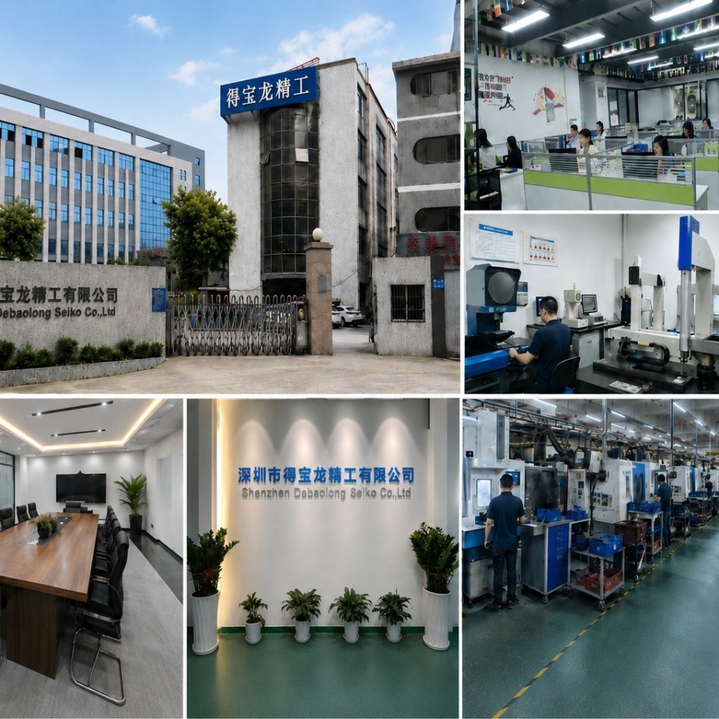
The factory collage shows building, workshop and manufacturing context.

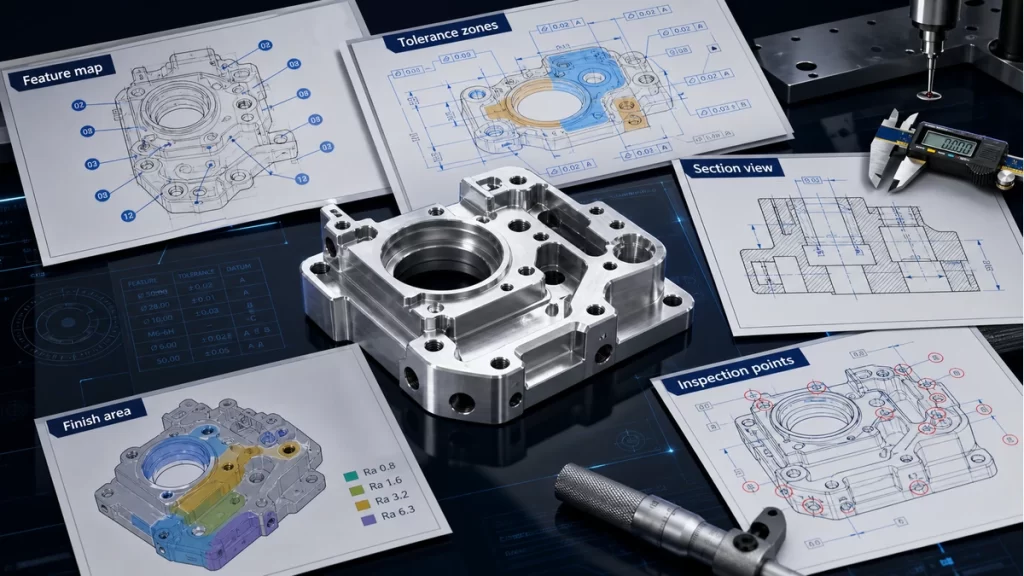
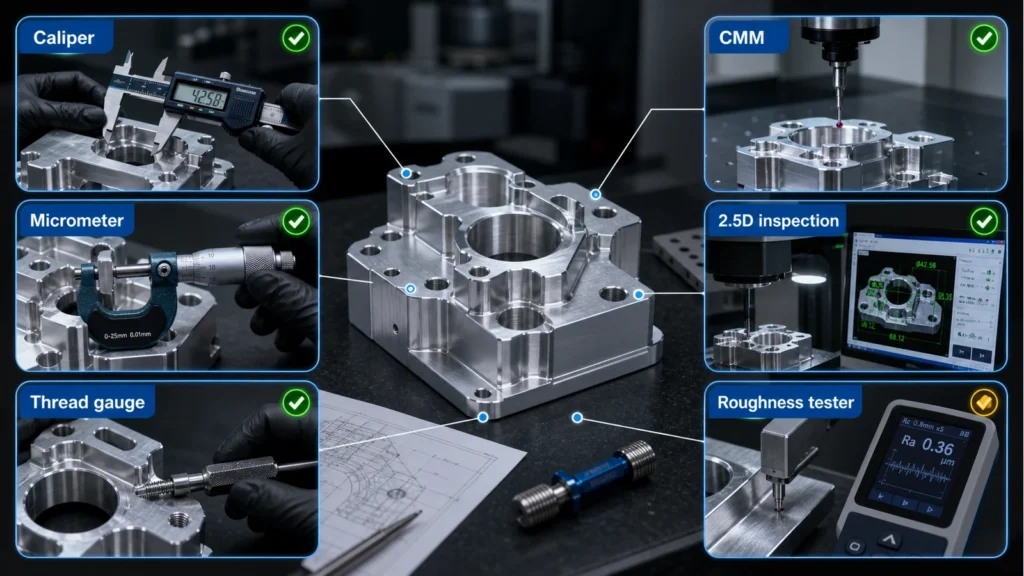
An illustrative planning graphic connects critical features, manufacturing decisions and engineering review. It is not a production inspection record.

Use Contact for general conversation or Engineering Review for a project-specific brief.

ADDITIVE

FDM

FDM builds thermoplastic parts layer by layer and exposes orientation and support decisions directly in the result.
Black thermoplastic bracket with visible extrusion layers and mounting holes
ENGINEERING DOSSIER

Resolve orientation, support, thermoplastic intent and post-process before an FDM build

Layer direction and support access

Identify load direction, visible surfaces and support contact before build orientation is finalized.

Walls, bridges and enclosed geometry

Review thin transitions, unsupported spans and spaces that may trap support or limit cleanup.

Material purpose

State whether the part is for visual iteration, fit checking or a selected functional evaluation and name the environmental priorities.

After-build fit and surface

Define insert, thread, mating and visible-surface expectations after support removal or other finishing.
MANUFACTURING ROUTE

Route logic for FDM

Identify load direction, visible surfaces and support contact before build orientation is finalized. State whether the part is for visual iteration, fit checking or a selected functional evaluation and name the environmental priorities.
Review thin transitions, unsupported spans and spaces that may trap support or limit cleanup. Best input: CAD plus use and orientation priorities.
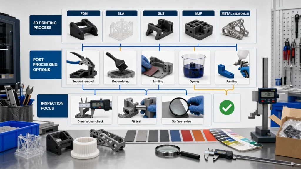
Post-processing and inspection diagram for 3D printed prototypes showing support removal, sanding, coating and dimensional checks
DECISION CONTROLS

Release controls specific to FDM

Best input

CAD plus use and orientation priorities

Key risk

Layer-sensitive features and support witness

Release evidence

Fit, interfaces and agreed surface
PROJECT-SPECIFIC DECISION DATA

Decision record before FDM release

Use this table to connect the process decision to the CAD, drawing and inspection evidence. Values remain project-specific until reviewed.
Decision itemWhat must be resolvedEvidence at release
Layer direction and support accessIdentify load direction, visible surfaces and support contact before build orientation is finalized.CAD plus use and orientation priorities
Walls, bridges and enclosed geometryReview thin transitions, unsupported spans and spaces that may trap support or limit cleanup.Layer-sensitive features and support witness
Material purposeState whether the part is for visual iteration, fit checking or a selected functional evaluation and name the environmental priorities.Fit, interfaces and agreed surface
After-build fit and surfaceDefine insert, thread, mating and visible-surface expectations after support removal or other finishing.Fit, interfaces and agreed surface
PART AND PROCESS EVIDENCE

FDM process, interface and inspection evidence

Black thermoplastic bracket with visible extrusion layers and mounting holes
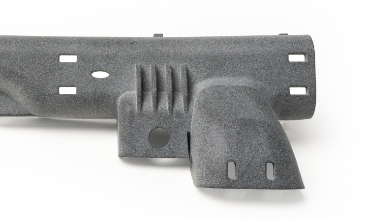
FDM sample showing visible layer lines around a curved arm and mounting holes. Build orientation and fit require part-specific review.
Post-processing and inspection diagram for 3D printed prototypes showing support removal, sanding, coating and dimensional checks
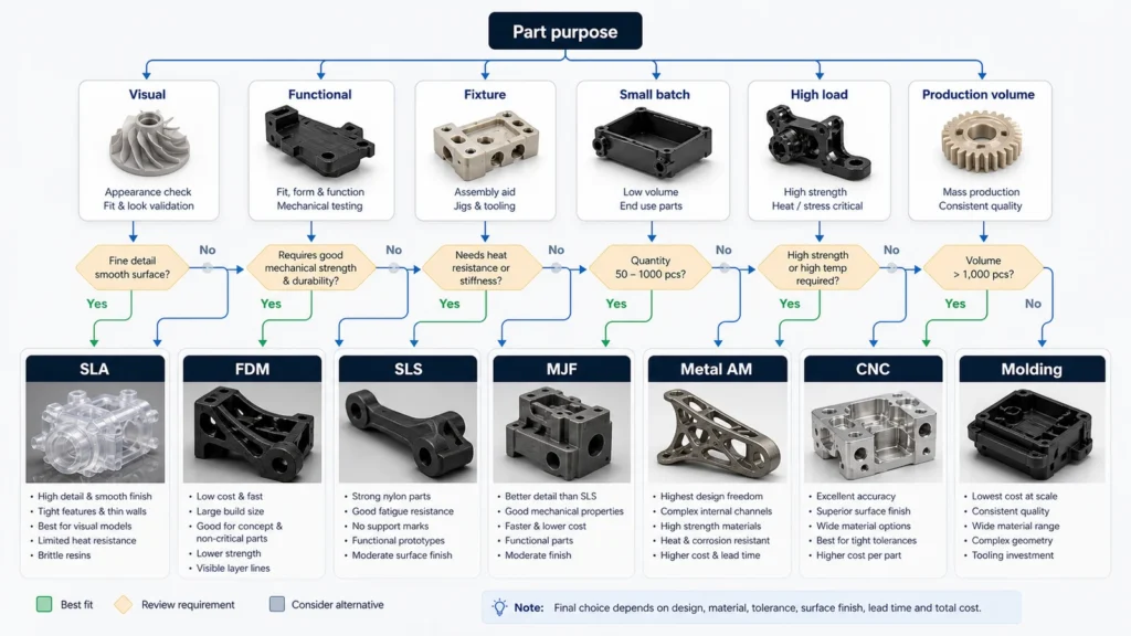
Decision tree for selecting a 3D printing process based on visual, functional, fixture, small batch and metal prototype needs
DECISION QUESTIONS

FDM route and release questions

What must be defined before reviewing FDM?

Identify load direction, visible surfaces and support contact before build orientation is finalized. Review thin transitions, unsupported spans and spaces that may trap support or limit cleanup.

Which interfaces need project-specific confirmation?

State whether the part is for visual iteration, fit checking or a selected functional evaluation and name the environmental priorities. Escalate Layer-sensitive features and support witness and any geometry, access, material or interface requirement that the drawing does not resolve.

What should accompany release?

Define insert, thread, mating and visible-surface expectations after support removal or other finishing. Fit, interfaces and agreed surface
PROJECT BRIEF

FDM project brief and release checklist

Use these page-specific checks to turn the FDM route into reviewable CAD, drawing and inspection inputs.

Geometry and route input — Layer direction and support access

Identify load direction, visible surfaces and support contact before build orientation is finalized. Include the relevant CAD orientation, interfaces and quantity in the review brief.

Release evidence — Walls, bridges and enclosed geometry

Review thin transitions, unsupported spans and spaces that may trap support or limit cleanup. Name the drawing dimensions and inspection evidence required at release.

RFQ handoff — Material purpose

State whether the part is for visual iteration, fit checking or a selected functional evaluation and name the environmental priorities. Upload controlled CAD/drawing inputs and state the unresolved route decision.