Machine vision systems depend on stable sensor and camera mounts. A camera can have the correct software and lens, but poor mounting hardware may still cause alignment drift, vibration, shadowing or difficult adjustment. Mounts must provide repeatable position, suitable stiffness and enough access for wiring, focus and maintenance.
Why Mounting Hardware Affects Vision Performance
Camera position, angle and vibration control affect image quality. If a mount flexes or shifts, the vision system may lose calibration. Sensor brackets also need stable alignment so trigger points and inspection positions remain consistent during production.
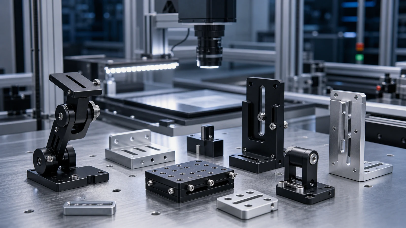
CNC Brackets and Adjustable Mounts
CNC machined brackets can provide accurate holes, slots, datum faces and compact geometry. Adjustable mounts may include slotted holes, clamp areas, dowel pins or modular interfaces. Debaolong supports these parts through CNC machining and inspection.
Alignment, Repeatability and Vibration
Mounts should have clear datum surfaces and enough stiffness for the application. Long unsupported arms can vibrate. Thin plates may deflect. Adjustment slots are useful, but they should lock securely after calibration. Fastener access must be practical for maintenance.
Material and Surface Finish
Aluminum is often used for lightweight sensor brackets. Stainless steel or coated steel may be used for stronger or harsher environments. Black anodizing or matte finishing may reduce glare near cameras, depending on the optical setup.
Compact Design Considerations
Machine vision mounts are often installed in tight spaces near conveyors, robots, lighting and guarding. Designers should check cable clearance, lens access, heat from lights and the direction needed for adjustment. Compact parts still need enough thickness around threads and slots.
Inspection and Assembly Checks
Inspection can include hole spacing, slot width, flatness, perpendicularity and thread quality. For adjustable mounts, the movement range and locking method should be confirmed during assembly.
Lighting, Cable Routing and Heat
Machine vision mounts are often installed near lights, moving axes and cable bundles. Designers should check whether the bracket blocks light, reflects into the lens or forces cables into a tight bend. If lights generate heat, the mount material and nearby plastic parts should be reviewed for temperature exposure.
Adjustment Features and Locking Methods
Adjustment can be helpful during setup, but the mount must lock firmly after calibration. Slots, clamp screws, dowel references and modular plates should be arranged so the technician can adjust the camera without losing the primary datum. If repeated replacement is expected, a hard stop or reference edge can reduce setup time.
Prototype Review Before Production
A prototype mount can be used to check image angle, cable routing, access and vibration. After testing, the production drawing should remove unnecessary temporary holes and confirm the final finish, material and inspection points. This keeps the production part clean and easier to manufacture.
Common Mounting Problems
Common machine vision mounting problems include long flexible arms, slots that cannot lock firmly, camera screws blocked by the bracket, cable exits that bend too tightly and reflective surfaces near the lens. These details can affect image stability even when the camera itself is correct. Reviewing the full camera, light and cable layout before manufacturing helps avoid repeated bracket revisions.
Inspection Priorities
Important inspection points usually include hole spacing, slot width, flatness of mounting faces and the angle between reference surfaces. If the mount includes a sliding adjustment, the movement range should be checked. If the part is used in several machines, repeatability between batches should be documented.
RFQ Checklist
- Camera or sensor model interface
- 2D drawings and 3D files
- Adjustment range and locking method
- Material and finish requirements
- Critical alignment surfaces
- Prototype or production quantity
How Debaolong Supports Vision Mount Projects
Debaolong can manufacture camera brackets, sensor mounts, adjustable plates and compact machined hardware for robotics and automation systems. These parts can be supported with machining, finishing and inspection based on project requirements.
FAQ
Why do camera mounts need stiffness?
Stiffness helps maintain calibration and reduces vibration during inspection or robotic motion.
Can sensor mounts be adjustable?
Yes. Slots, clamp features and modular plates can provide adjustment if the locking method is stable.
Is black anodizing useful for vision parts?
It can be useful when glare control is important, depending on lighting and camera position.
Can Debaolong support small batches?
Yes. Debaolong can support prototype and small-batch sensor mounts according to drawings.
Need custom sensor or camera mounts? Send drawings and interface requirements through the Robotics & Automation Components page.
Related Engineering Resources