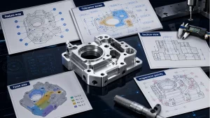
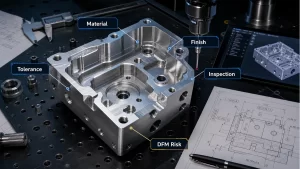
A practical GD&T straightness guide explaining surface straightness, axis straightness, tolerance zones, drawing callouts, material modifiers and inspection methods for machined parts.
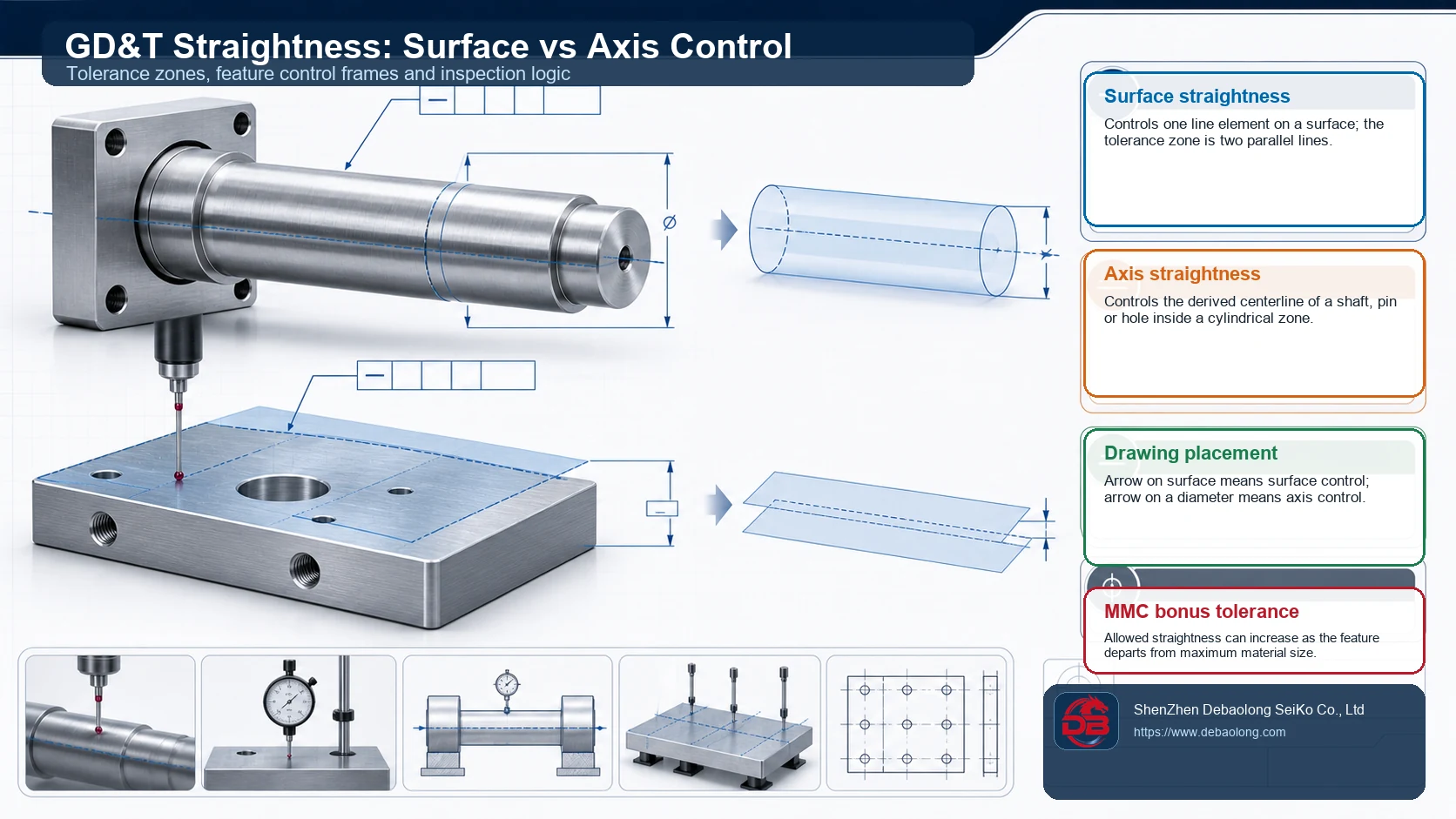
What Straightness Controls
Straightness is a GD&T control for how much a line element may deviate from an ideal straight line. In production drawings it is deceptively simple, but its meaning changes depending on where the callout is applied. A straightness control attached to a surface limits individual line elements on that surface. A straightness control attached to a diameter or cylindrical feature controls the derived centerline of the feature instead of the visible outside surface.
For CNC components, this difference affects both machining strategy and inspection cost. A general size tolerance may be enough for nonfunctional surfaces, while sliding shafts, guide pins, sealing lands and bearing fits often need a more explicit straightness requirement. When straightness is part of a larger tolerance stack, it should be evaluated together with CNC machining tolerances instead of added as a reflexive drawing note.
Surface Straightness vs Axis Straightness
Surface straightness creates a two-dimensional tolerance zone made from two parallel lines. Each controlled line element on the surface must stay between those limits. This is useful for milled edges, long flat bearing strips, rail contact lines and local surface features where the designer cares about one trace rather than the whole plane.
Axis straightness is different. It places the derived median line of a cylindrical feature inside a cylindrical tolerance zone. The part may still show normal roundness variation, but the centerline cannot wander beyond the specified cylinder. This is why axis straightness is common on shafts, bores, dowel holes and rotating parts where alignment matters more than the appearance of one surface trace.
How to Call It Out on Drawings
A surface straightness callout is usually placed with a leader arrow pointing directly to the controlled surface. Axis straightness is normally associated with the feature of size, often through a feature control frame connected to the diameter dimension. The distinction must be visible on the drawing; otherwise inspection teams may measure the wrong element and reject good parts or accept bad ones.
Straightness should also be consistent with drawing standards. If a drawing mixes tight straightness, broad profile controls and unclear datum references, the supplier may need clarification before quoting. For reference, DEBAOLONG’s guide to CNC machining tolerance standards explains how ISO and ASME-style tolerancing decisions affect manufacturing interpretation.
Tolerance Zones and Material Modifiers
For a surface, the zone is two parallel lines separated by the straightness value. For an axis, the zone is a cylinder whose diameter equals the tolerance. When a maximum material condition modifier is permitted on an axis straightness callout, bonus tolerance can become available as the feature departs from maximum material size. That makes sense for assembly features because extra clearance can absorb more centerline deviation without hurting fit.
Bonus tolerance should not be used casually. It works only when the functional requirement allows it and when inspection can verify the feature size and geometric error together. If the part must guide a bearing, seal against pressure or maintain optical alignment, the engineering team should confirm that bonus tolerance will not compromise the real function.
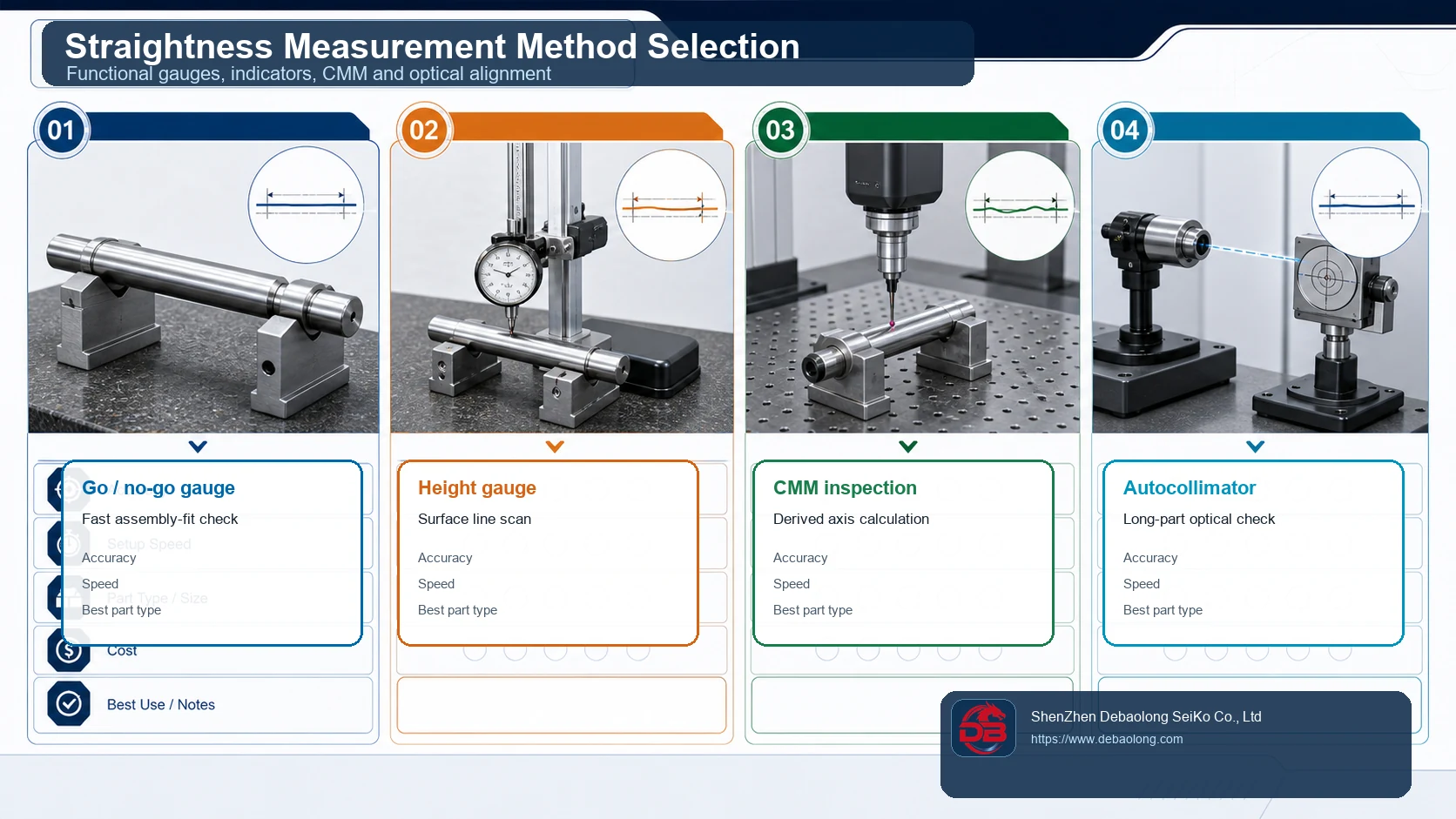
Measurement Method Selection
Straightness can be inspected with simple gauges, dial indicators, height gauges, CMM programs or optical methods. The right choice depends on the feature, tolerance value, part length, surface finish and production volume. A go/no-go gauge can be fast for repetitive assembly checks, while a CMM is better when the derived axis or multiple datum relationships must be calculated.
Long shafts often need V-blocks, indicators and rotation checks to separate straightness from runout. Flat surfaces may need a height gauge or scanning routine across selected line elements. Optical alignment can be useful for long features where a contact probe is slow or mechanically awkward.
Straightness in Manufacturable CNC Design
A strict straightness number is not automatically better. It may require different fixturing, extra stress relief, slower finishing passes, more inspection time or a change in material form. Before tightening the callout, check whether the functional issue could be solved with datums, flatness, cylindricity, runout or a clearer fit requirement. Many expensive tolerancing problems begin as small CAD and drawing mistakes, a pattern covered in DEBAOLONG’s CNC CAD mistake guide.
The best drawing tells the manufacturer what must be controlled, where it matters, how it will be inspected and where normal variation is acceptable. Straightness is powerful because it is narrow and specific. Used carefully, it improves function without forcing every surface on the part into unnecessary precision.
Related Engineering Resources