A professional CNC milling guide covering machine components, CAD-to-CAM workflow, G-code, setup, spindle speed, feed rate, chip load, cutting depth and common milling operations.
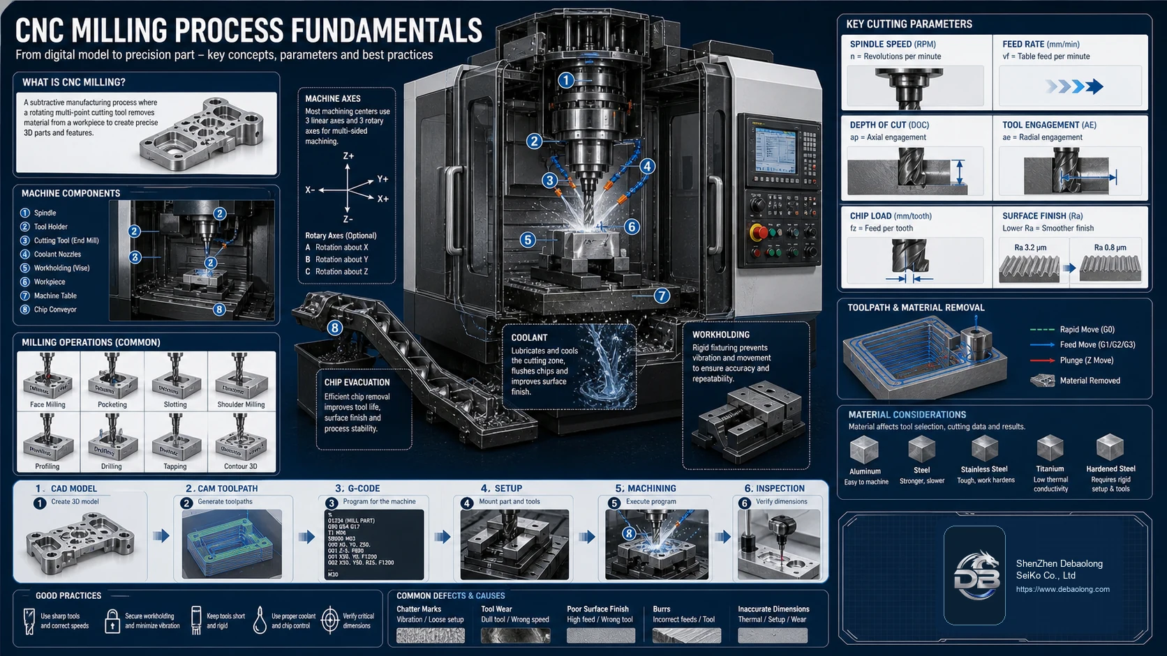
What CNC Milling Does
CNC milling is a subtractive machining process where rotating cutting tools remove material from a workpiece to create precise shapes, pockets, holes, slots, profiles and surfaces. It is one of the most flexible methods for metal and plastic parts because toolpaths can be adapted to many geometries.
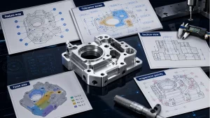
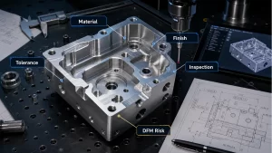
Milling decisions connect directly to tolerance, surface finish and cost. For precision parts, review the process alongside DEBAOLONG’s CNC machining tolerance guide.
From CAD to Machining
The workflow begins with a CAD model, then moves into CAM toolpaths, G-code generation, machine setup, machining and inspection. Each step can introduce risk if geometry, tooling, workholding or inspection strategy is unclear.
Workholding is especially important. A rigid setup reduces vibration, improves repeatability and protects surface finish. Coolant and chip evacuation help control heat, tool wear and burr formation.
Cutting Parameters
Spindle speed, feed rate, chip load, depth of cut and tool engagement determine how the cutter interacts with the material. Aggressive settings may remove material quickly but increase tool wear, chatter or poor surface finish. Conservative settings may improve stability but increase cycle time.
Tool access and feature geometry are common cost drivers. Deep pockets, sharp internal corners and small tools can raise machining time, a pattern covered in DEBAOLONG’s CNC CAD mistake guide.
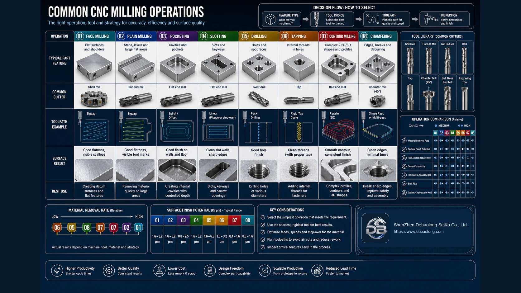
Common Milling Operations
Face milling creates flat datum surfaces. Pocketing removes internal material. Slotting cuts narrow openings. Drilling and tapping create holes and threads. Contour milling follows profiles and 3D shapes. Chamfering breaks edges and improves assembly safety.
Choosing the right operation depends on feature type, tolerance, material, tool rigidity, setup access and inspection method. A good CAM plan avoids air cuts, reduces unnecessary tool changes and keeps the shortest rigid tool practical.
Process Selection
Milling is excellent for precise 3D features, tight fits and strong materials. For flat profiles or heat-sensitive sheet and plate components, a cold cutting option may be more appropriate; DEBAOLONG’s waterjet cutting overview explains that alternative.
Related Engineering Resources