CNC machined brackets are small but critical parts in robotic systems, automation machinery and motion assemblies. They hold motors, sensors, actuators, grippers, guards and alignment hardware in the correct position. A bracket that is too weak, too heavy or poorly aligned can create vibration, assembly errors or early wear. A good design balances stiffness, weight, accuracy and manufacturability.
Why Brackets Matter in Robotic Systems
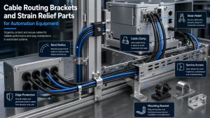
Robotic brackets often transfer load between moving parts, fixed frames and tooling interfaces. They may support cameras, pneumatic parts, cable carriers, reducers, motors or end effectors. In automation equipment, brackets also define datum locations for repeated operation. A slight hole shift or weak support can affect the repeatability of the whole system.
Common Robotic Bracket Types
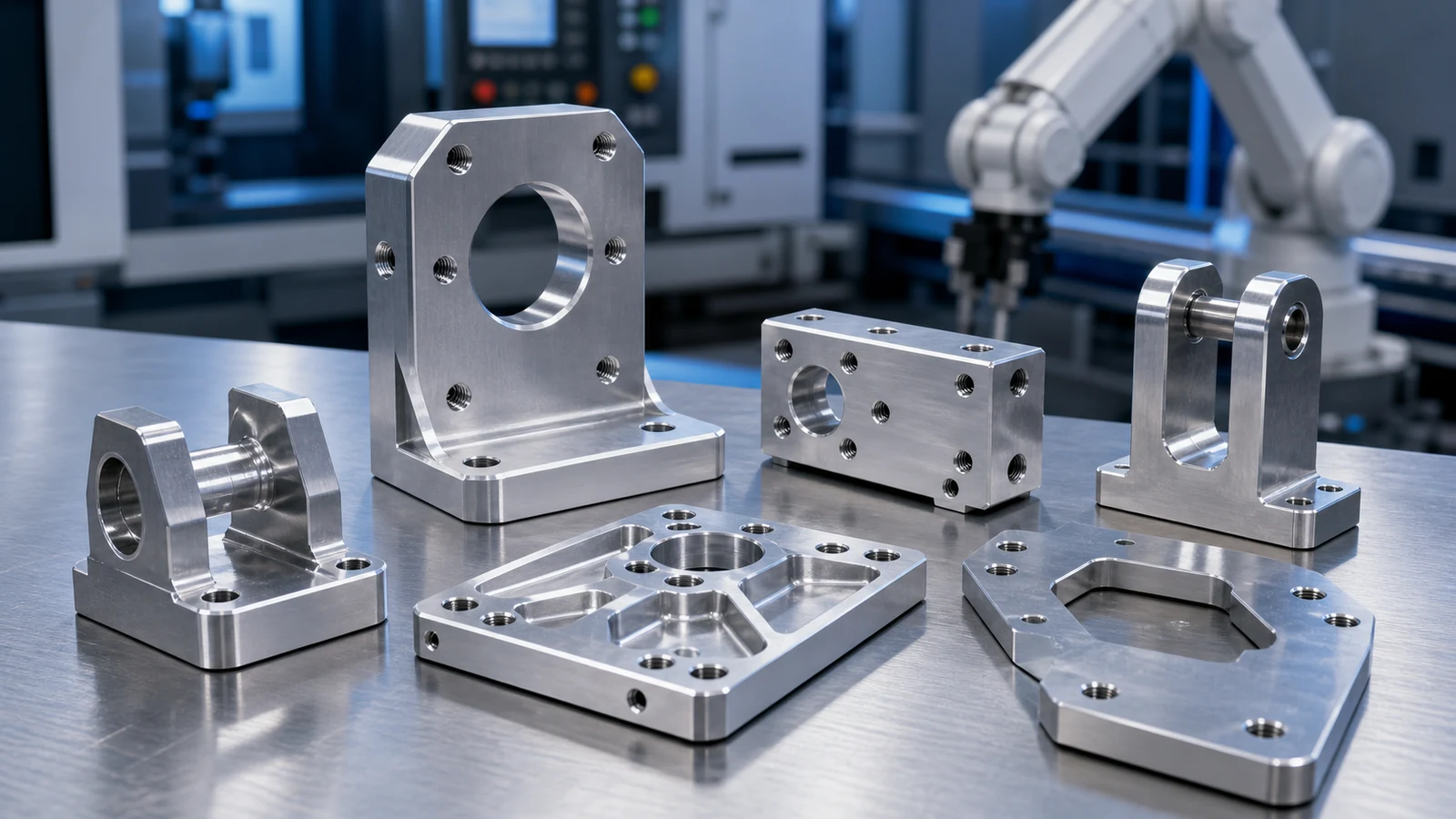
Common parts include motor plates, sensor brackets, adapter blocks, actuator mounts, rail supports, lightweight side plates and positioning blocks. Debaolong supports these parts through CNC machining, surface finishing and inspection according to customer drawings.
Material Selection
Aluminum is widely used because it is light, easy to machine and suitable for anodizing. Stainless steel can be selected when strength, wear or corrosion resistance is important. Carbon steel may be suitable for coated structural brackets. Material choice should consider load, weight, vibration, corrosion, fastening force and production quantity.
Mounting Holes, Threads and Alignment
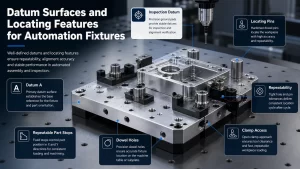
Hole position, thread depth, counterbores and datum surfaces should be clearly defined. If a bracket holds a camera or robot tool, alignment faces may need tighter control than outside cosmetic faces. Threaded holes should have enough engagement depth and clearance for assembly tools.
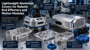
Lightweighting and Rigidity
Weight reduction is common in robotic hardware, but excessive pockets can reduce stiffness or increase machining time. Fillets, ribs and relieved areas should be designed with tool access and clamping in mind. Designers should avoid deep narrow pockets if a simpler relieved shape can meet the function.
Surface Finishing and Inspection
Anodizing, hard anodizing, passivation, plating or coating may be used depending on material and environment. Inspection can include hole spacing, flatness, perpendicularity, thread checks and assembly fit. Critical alignment areas should be marked on the drawing.
DFM Notes for Machined Robotic Brackets
Design for manufacturing should start with tool access and clamping. Deep pockets, thin walls, very small internal radii and unnecessary cosmetic surfaces can increase machining time. If the bracket is only functional on two or three faces, the drawing should not require tight control on every outside edge. Practical datum selection helps the supplier inspect the same features that matter to assembly.
Prototype and Production Planning
A prototype bracket may be machined quickly to confirm robot reach, cable clearance and fastening. Production brackets may need fixture planning, repeat inspection and more stable finishing requirements. When the design moves from prototype to production, review which features were only useful for testing and which features are required in the final hardware.
Assembly and Packaging Considerations
Robotic brackets often ship with finished surfaces, threaded holes and alignment faces that must not be damaged. Packaging should prevent metal-to-metal contact when anodized or plated surfaces are important. Assembly notes should also clarify whether fasteners, dowel pins, inserts or bushings are supplied by the customer or expected as part of the manufacturing package.
Typical Drawing Mistakes to Avoid
Common problems include missing thread depth, unclear datum references, very tight tolerances on non-functional edges, and holes placed too close to thin walls. Another common issue is designing a part around a square internal corner that cannot be machined with a standard cutter. Adding practical radii and showing which surfaces control the robot alignment can reduce quotation time and avoid unnecessary cost.
RFQ Checklist
- 2D drawings and 3D CAD files
- Material and finish requirements
- Critical datum surfaces and hole locations
- Thread specifications and inserts if required
- Prototype or production quantity
- Inspection report requirements
How Debaolong Supports Robotics Brackets
Debaolong can support CNC machined brackets, mounting plates and support blocks from prototype to production. For tolerance planning, see the CNC machining tolerance guide or review the Robotics & Automation Components solution page.
FAQ
What material is best for robotic brackets?
Aluminum is common for lightweight parts, while stainless steel or carbon steel may be selected for strength, wear or environmental needs.
Do all bracket surfaces need tight tolerances?
No. Tight tolerances should be reserved for datum faces, alignment holes and functional mounting surfaces.
Can CNC brackets be anodized?
Yes. Aluminum brackets can often be anodized, but masking and contact surfaces should be discussed if needed.
Can Debaolong make prototype and production brackets?
Yes. Debaolong can support prototype batches, small production runs and repeat manufacturing according to drawings.
Need custom robotic brackets? Send drawings, STEP files, material, tolerance and finish requirements through the Robotics & Automation Components page.
Related Engineering Resources