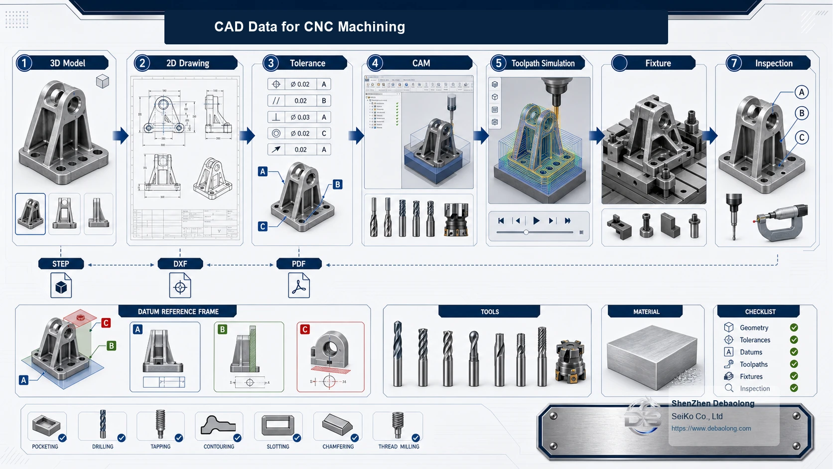
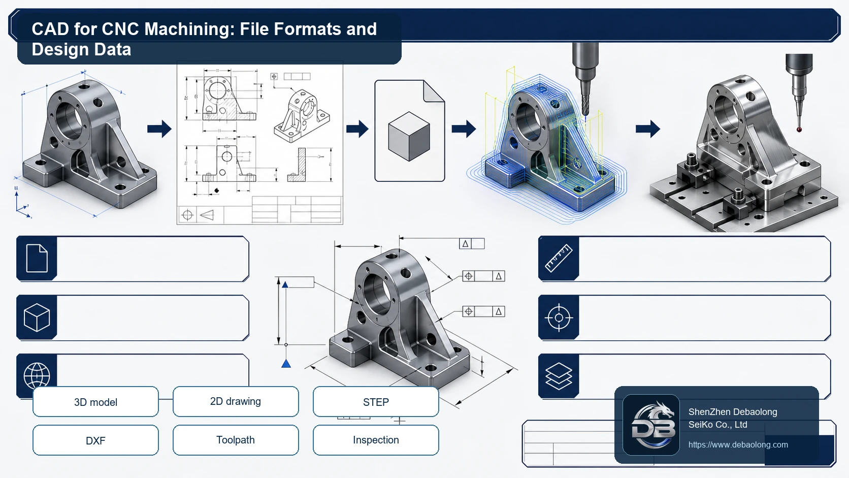
CAD for CNC machining is more than a 3D shape. It must communicate dimensions, tolerances, materials, surface finish, threads, datum references and any special inspection requirements. The source article explains CAD, common file formats and how design data connects to CNC manufacturing. For DEBAOLONG’s CNC machining workflow, a clean 3D model plus a clear drawing helps reduce quoting questions, programming risk and inspection uncertainty. The best file package tells manufacturing what to cut, what to measure, what material to buy and which surfaces matter most. It also separates cosmetic expectations from functional dimensions and inspection priorities.
CAD Must Communicate Manufacturing Intent
A model can show geometry, but it may not show what matters most. Critical fits, cosmetic faces, heat treatment, coating and post-machining requirements often need written drawing notes.
What CAD Does
CAD uses computer models to create, modify, analyze and optimize a design. Mechanical CAD can define parts and assemblies with curves, surfaces, solids and parameters. Simulation or analysis tools can then evaluate loads, motion or interference before manufacturing.
In manufacturing, CAD output becomes the foundation for CAM programming, toolpath planning, fixturing, inspection and procurement. Poor CAD data creates hidden cost because every supplier must interpret missing information.
DWG, DXF, DGN, STL and STEP
DWG stores 2D and 3D drawing data and metadata. DXF is a more exchange-friendly drawing format. DGN is associated with certain design and infrastructure workflows. STL represents triangulated surface geometry and is common in 3D printing, but it usually lacks precise manufacturing intelligence.
STEP is often preferred for CNC machining because it can preserve accurate 3D solid geometry across CAD systems. However, STEP still does not replace a drawing when tolerances, threads, finishes or material requirements are important.
CAD and CNC Machining
CNC machining needs model accuracy, tool access, machinable internal radii, reachable features and clear setup logic. Small CAD issues can force small tools, extra setups, EDM, hand finishing or unclear inspection.
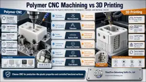
Material data should be clear before quoting. A bracket in aluminum 6061, stainless steel 316 and POM plastic may have the same shape but very different cycle time, tolerance behavior and finishing route. Use all materials to keep the material decision visible.
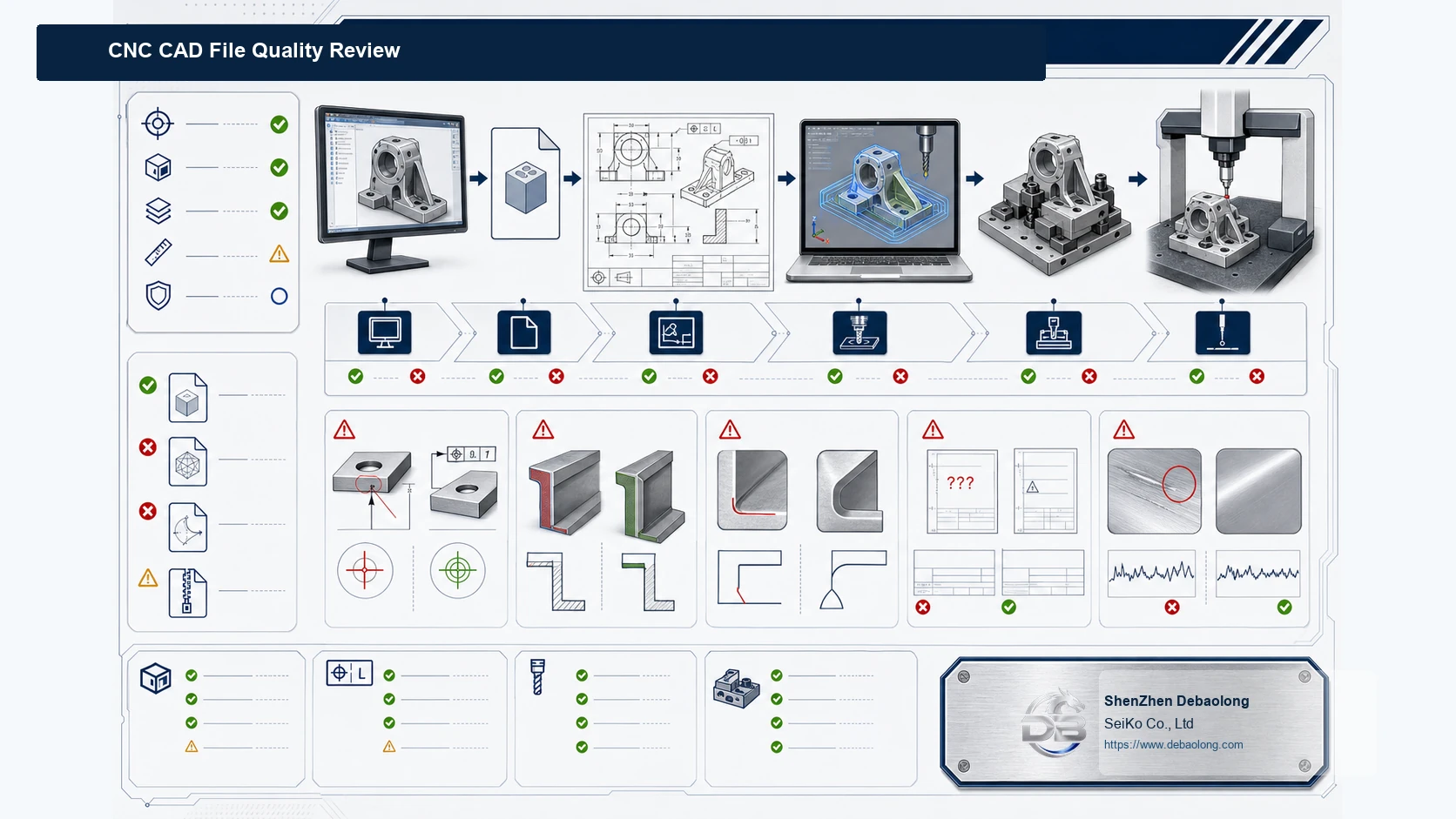
DEBAOLONG File Review
DEBAOLONG reviews CAD files for geometry, manufacturing notes, tolerance, surface finish, material, threads and inspection needs. For more drawing and process planning guidance, see the manufacturing engineering knowledge center.
Related Services
For related manufacturing support, review CNC machining, sheet metal fabrication, and 3D printing services, with injection molding support available for plastic production programs.