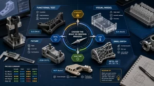
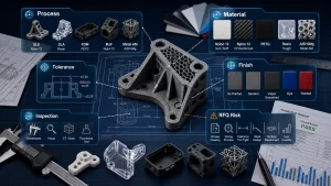
MJF 3D printing is powerful for functional nylon parts, but design quality depends on dimensions, detail size, tolerance, wall thickness, lattice structure, assemblies, hollow sections, glue lines, ducts and part orientation. The source article organizes these topics as design guidelines, and they are exactly the points DEBAOLONG checks before printing nylon parts through 3D printing. A good MJF design uses the powder-bed process rather than fighting it. In practice, the best choice is the process route that meets the real engineering requirement while keeping tolerance, finish, inspection, application risk and lead time under control before production begins.
MJF Design Is About Powder, Heat and Nylon Behavior
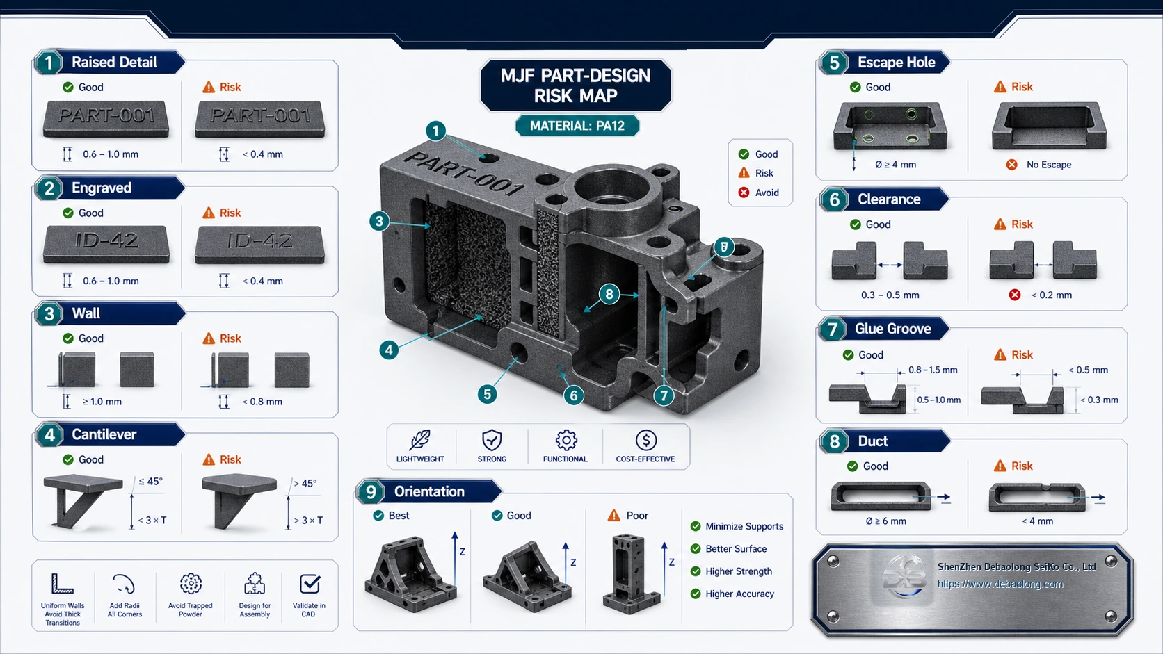
MJF can build complex nylon geometry without conventional supports, but the part still needs powder removal, thermal stability, clearance and inspection planning.
Details, Tolerances and Solid vs Lattice Parts
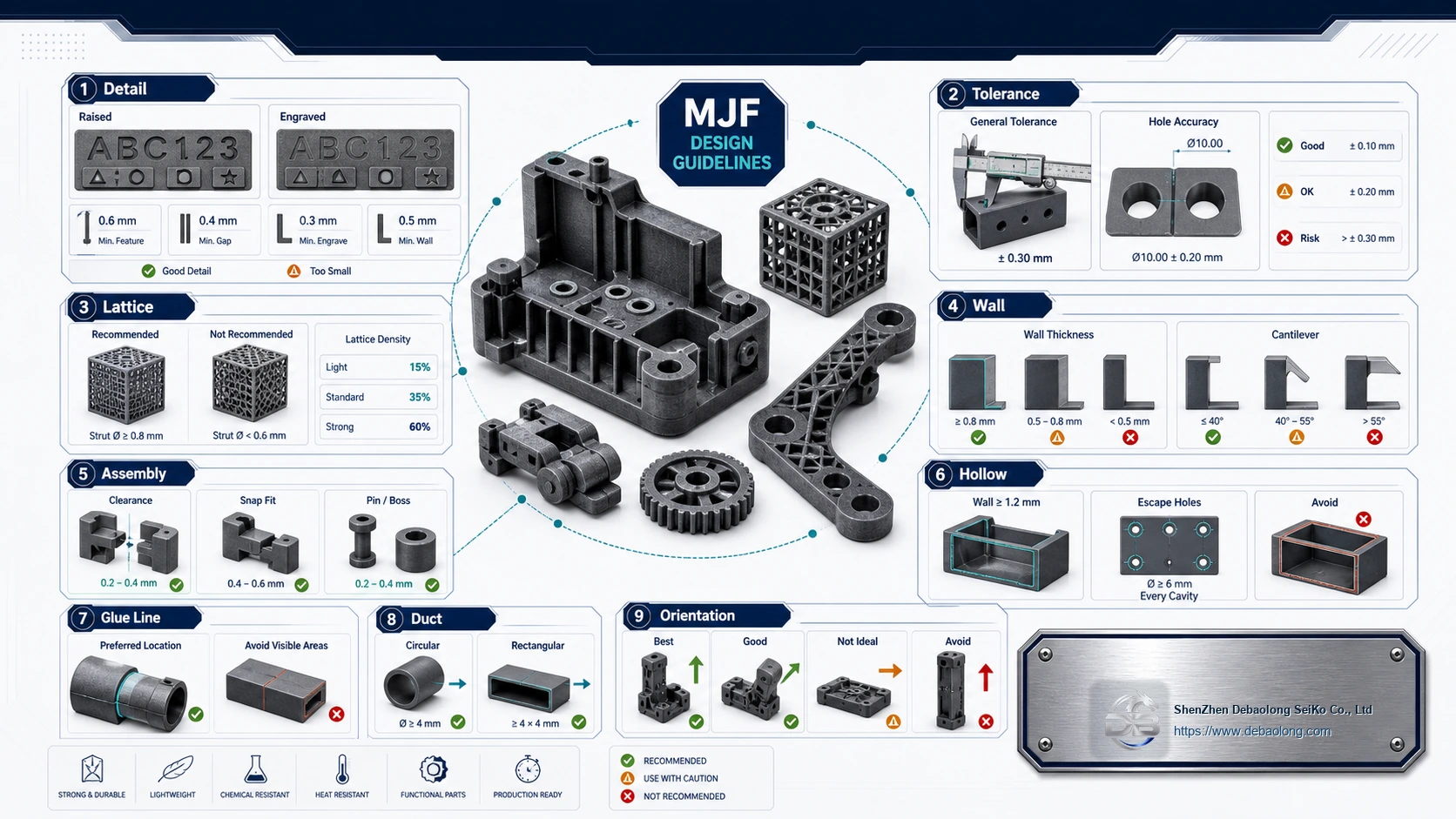
Raised and engraved details should be large enough to survive printing, depowdering and finishing. Small text or shallow engraving may blur or disappear. Tolerances depend on size, orientation, material and post-processing.
Solid parts are stronger but heavier and may trap heat. Lattice or structural infill can reduce weight and material use, but the lattice must still be cleanable and strong enough for the application.
Walls, Assemblies and Hollow Parts
Thin walls and cantilevers need minimum thickness and support from the geometry. Assemblies require designed clearance so parts do not fuse, rub or seize after printing.
Hollow enclosed parts need escape holes for powder removal. Without access, trapped powder adds weight, contamination risk and inspection problems.
Glue Lines, Ducts and Orientation
Glue grooves, ducts and channels should be sized for manufacturing and cleaning. PA12, filled nylon and flexible materials each behave differently, so compare options in all materials before finalizing the design.
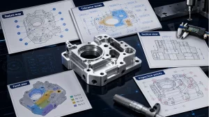
Orientation affects surface quality, strength and dimensional behavior. Mark cosmetic faces and critical interfaces so the build can be planned correctly.
DEBAOLONG MJF Review
DEBAOLONG reviews MJF designs for detail, tolerance, powder removal, wall thickness, assembly clearance and finish. The knowledge center can help compare MJF with SLS, SLA, FDM and CNC machining.
Related Services
Related DEBAOLONG capabilities include 3D printing, CNC machining, sheet metal fabrication, injection molding, material selection support and manufacturing engineering review.