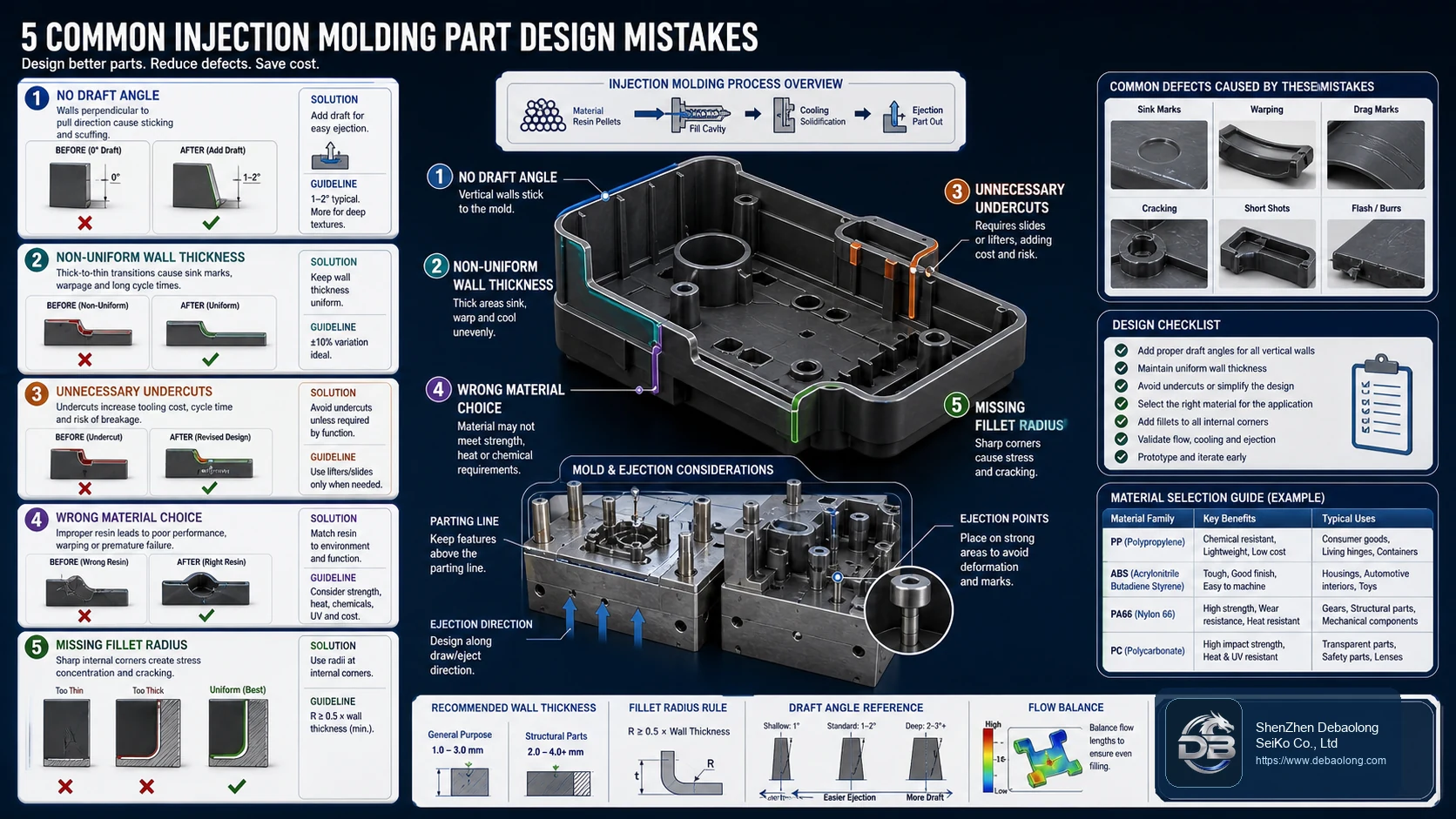
A practical injection molding DFM guide covering missing draft, non-uniform wall thickness, unnecessary undercuts, wrong material selection and missing fillet radii.
Mistakes Become Tooling Cost
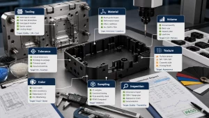
Injection molded parts must be designed for the mold, the resin and the ejection process. A feature that looks harmless in CAD can create tool complexity, sink marks, warpage, drag marks, cracking or repeated production scrap.
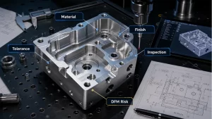
These mistakes should be corrected before tool design. Once steel is cut, even small changes can become expensive. This is why injection molding design belongs inside a full DFM review rather than a late drawing check.
Missing Draft and Uneven Walls
Vertical walls without draft can stick to the mold and show drag marks during ejection. Textured surfaces and deep ribs usually need more draft than polished shallow features. Draft should follow the mold opening direction and be reviewed with parting line decisions.
Non-uniform wall thickness causes uneven cooling. Thick areas can create sink marks and voids, while abrupt transitions increase stress and warpage. Ribs, bosses and local reinforcement are usually better than simply making the whole wall thicker.
Undercuts, Materials and Radii
Undercuts may require lifters, slides, collapsible cores or secondary operations. Sometimes they are necessary, but many are accidental CAD choices that can be redesigned for simpler tooling.
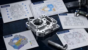
Material selection affects shrinkage, stiffness, heat resistance, chemical exposure and surface quality. Pair material decisions with tolerance expectations using DEBAOLONG’s injection molding tolerance guide.
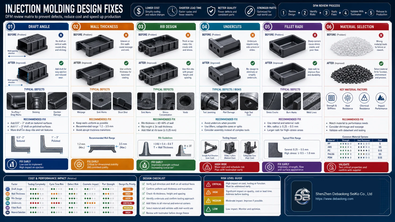
Fillets and Stress
Sharp internal corners concentrate stress and can block smooth plastic flow. Fillet radii improve flow, reduce cracking and make the part more durable. The radius should be large enough to matter but consistent with wall thickness and tooling access.
Fix Early
Most molded-part design problems are cheapest to fix before quoting and tooling. The same early-correction logic appears in CNC as well; DEBAOLONG’s CAD mistake guide shows how small geometry choices can drive cost across manufacturing processes.
Related Engineering Resources